使用FOC电流进行扭矩控制
这种扭矩控制模式允许你对无刷直流电机进行真正的扭矩控制,并且需要电流传感来实现。用户设置目标电流\(I_d\),FOC算法通过测量相电流(\(i_a\)、\(i_b\)和\(i_c\))和转子角度\(a\),计算出维持该电流所需的相电压\(u_a\)、\(u_b\)和\(u_c\)。启用此模式的方式如下:
// FOC current torque control mode
motor.torque_controller = TorqueControlType::foc_current;
具体工作原理
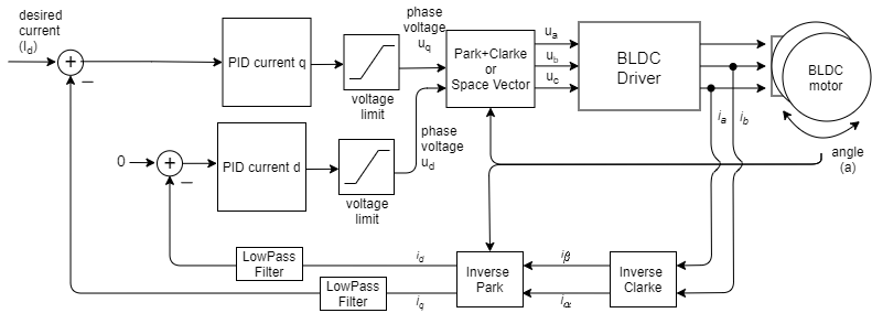

FOC电流扭矩控制算法读取无刷直流电机的相电流(\(i_a\)、\(i_b\)和\(i_c\))。相电流通过逆克拉克变换转换为电流\(i_\alpha\)和\(i_\beta\)。例如,如果测量到相电流\(i_a\)和\(i_b\)(由于三相电流之和为零,\(i_c=-i_a-i_b\)): \(i_\alpha = i_a, \quad i_\beta = i_a\frac{1}{\sqrt{3}} + i_b\frac{2}{\sqrt{3}}\)
利用当前转子角度\(a\)以及电流\(i_\alpha\)和\(i_\beta\),FOC算法通过逆帕克变换计算出电流的\(i_d\)和\(i_q\)分量。
\[i_q = i_\beta \cos(a) - i_\alpha \sin(a), \quad i_d = i_\alpha \cos(a) + i_\beta \sin(a)\]利用目标电流值\(I_d\)(d表示期望的)以及测量到的电流\(i_q\)和\(i_d\),每个轴的PID控制器计算出要施加到电机的适当电压\(U_q\)和\(U_d\),以维持\(i_q\)=\(I_d\)和\(i_d\)=0。
\[U_q = \text{PID}_q(I_d - i_q), \quad U_d = \text{PID}_d(0-i_d)\]最后,FOC算法使用帕克+克拉克(或空间矢量)变换,为电机设置适当的\(u_a\)、\(u_b\)和\(u_c\)电压。通过测量相电流,这种扭矩控制算法确保这些电压在电机转子中产生适当的电流和磁力,且与永磁体磁场正好成90度偏移,这保证了最大扭矩,这一过程称为换相。
电机产生的扭矩与q轴电流\(i_q\)成正比(与扭矩常数\(K_t\)相关)。因此,对于任何目标电机扭矩\(\tau\),目标电流\(I_d\)可计算为:
\[I_d = \frac{\tau}{K_t}\]配置参数
为了使这个控制环平稳运行,用户需要配置PID_current_q的PID控制器参数和低通滤波器LPF_current_q的时间常数。
// Q axis
// PID parameters - default
motor.PID_current_q.P = 5;                       // 3    - Arduino UNO/MEGA
motor.PID_current_q.I = 1000;                    // 300  - Arduino UNO/MEGA
motor.PID_current_q.D = 0;
motor.PID_current_q.limit = motor.voltage_limit;
motor.PID_current_q.ramp = 1e6;                  // 1000 - Arduino UNO/MEGA
// Low pass filtering - default
LPF_current_q.Tf= 0.005;                         // 0.01 - Arduino UNO/MEGA

// D axis
// PID parameters - default
motor.PID_current_d.P = 5;                       // 3    - Arduino UNO/MEGA
motor.PID_current_d.I = 1000;                    // 300  - Arduino UNO/MEGA
motor.PID_current_d.D = 0;
motor.PID_current_d.limit = motor.voltage_limit;
motor.PID_current_d.ramp = 1e6;                  // 1000 - Arduino UNO/MEGA
// Low pass filtering - default
LPF_current_d.Tf= 0.005;                         // 0.01 - Arduino UNO/MEGA
扭矩控制示例代码
一个简单的基于 FOC 电流的扭矩控制示例,使用内置电流传感器并通过串行命令接口设置目标值。
#include <SimpleFOC.h>
// BLDC motor & driver instance
BLDCMotor motor = BLDCMotor(11);
BLDCDriver3PWM driver = BLDCDriver3PWM(9, 5, 6, 8);
// encoder instance
Encoder encoder = Encoder(2, 3, 500);
// channel A and B callbacks
void doA(){encoder.handleA();}
void doB(){encoder.handleB();}
// current sensor
InlineCurrentSense current_sense = InlineCurrentSense(0.01, 50.0, A0, A2);
// instantiate the commander
Commander command = Commander(Serial);
void doTarget(char* cmd) { command.scalar(&motor.target, cmd); }
void setup() {
// initialize encoder sensor hardware
encoder.init();
encoder.enableInterrupts(doA, doB);
// link the motor to the sensor
motor.linkSensor(&encoder);
// driver config
// power supply voltage [V]
driver.voltage_power_supply = 12;
driver.init();
// link driver
motor.linkDriver(&driver);
// link the driver to the current sense
current_sense.linkDriver(&driver);
// current sense init hardware
current_sense.init();
// link the current sense to the motor
motor.linkCurrentSense(¤t_sense);
// set torque mode:
motor.torque_controller = TorqueControlType::foc_current;
// set motion control loop to be used
motor.controller = MotionControlType::torque;
// foc current control parameters (Arduino UNO/Mega)
motor.PID_current_q.P = 5;
motor.PID_current_q.I= 300;
motor.PID_current_d.P= 5;
motor.PID_current_d.I = 300;
motor.LPF_current_q.Tf = 0.01;
motor.LPF_current_d.Tf = 0.01;
// use monitoring with serial
Serial.begin(115200);
// comment out if not needed
motor.useMonitoring(Serial);
// initialize motor
motor.init();
// align sensor and start FOC
motor.initFOC();
// add target command T
command.add('T', doTarget, "target current");
Serial.println(F("Motor ready."));
Serial.println(F("Set the target current using serial terminal:"));
_delay(1000);
}
void loop() {
// main FOC algorithm function
motor.loopFOC();
// Motion control function
motor.move();
// user communication
command.run();
}