反作用轮倒立摆项目
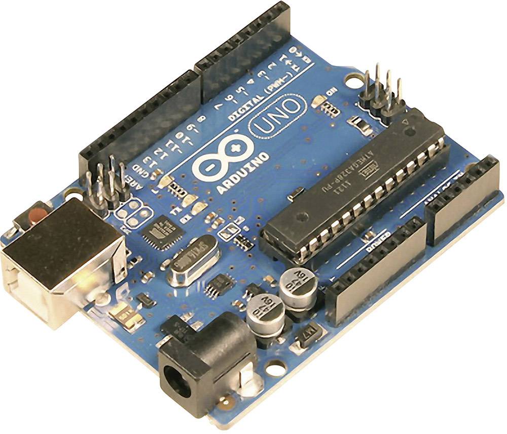
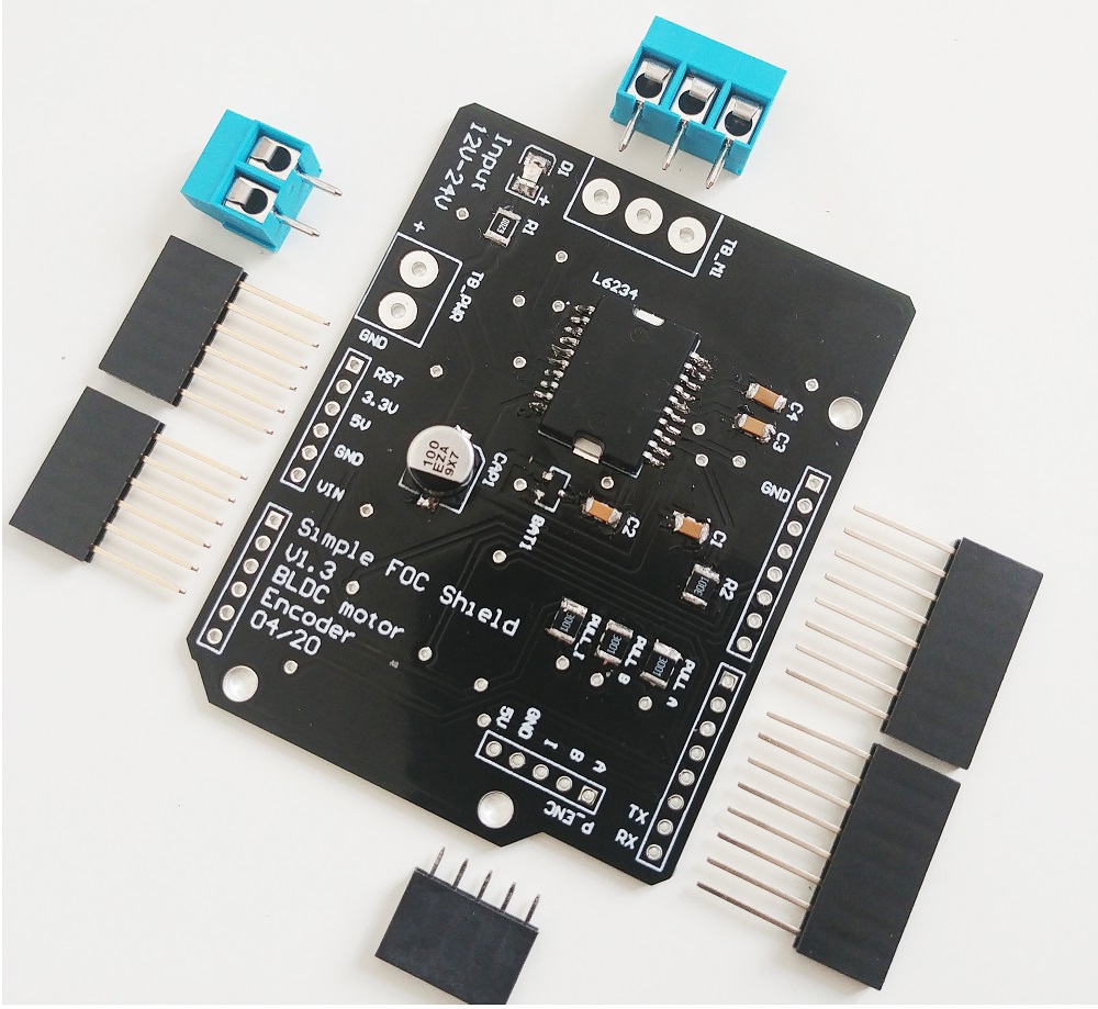
使用 简易FOC shield
这是一个完全基于 Arduino SimpleFOC 库和 SimpleFOC 屏蔽板 设计和控制反作用轮倒立摆的项目。


这个项目在很多方面都非常有趣,它适合:
- 寻找高级算法测试平台的学生
- 有空闲时间且有动力创造酷东西的所有人 :D
YouTube 演示视频 😃
但对我来说,这个项目最令人兴奋的部分是能够使用磁场定向控制算法。
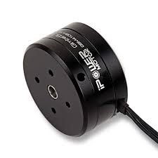
在这个项目中使用无刷直流电机的主要好处是:
- 高扭矩重量比
- 越轻越好
- 低角速度下有很大的扭矩
- 不需要将电机旋转到很高的转速就能获得高扭矩
- 没有齿轮箱和间隙
- 运行非常平稳 = 非常稳定的摆
到目前为止,由于硬件的复杂性和成本,以及缺乏用户友好、文档完善的软件,FOC 一直局限于高端应用。因此,我非常高兴向您展示这样的项目,它们直接受益于 FOC 算法和无刷直流电机,并鼓励您在您的项目中使用这些技术。
需要哪些组件?

由于使用了无刷电机和 简易FOC屏蔽板,这可能是反作用轮倒立摆最简单的硬件设置之一。

有关 3D 打印组件和硬件的更多详细信息,请查看该项目的 github 存储库。
连接所有组件
除了这个项目的几个 3D 打印组件、几个螺丝和轴承外,您还需要这些组件:
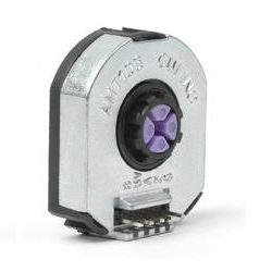
编码器 1(电机)
- 通道
A和B连接到编码器连接器P_ENC的端子A和B。
编码器 2(摆)
引脚限制
Arduino UNO 没有足够的硬件中断引脚用于两个编码器,因此我们需要使用软件中断库。
- 编码器通道
A和B连接到引脚A0和A1。
电机
- 电机相
a、b和c直接连接到电机端子连接器TB_M1
Arduino 代码
让我们浏览这个项目的完整代码并一起编写它。
首先,您需要包含 SimpleFOC 库:
#include <SimpleFOC.h>
确保您已经安装了该库。如果还没有安装,请查看 入门页面。
在这种情况下,我们使用两个编码器,因此我们需要一个软件中断库。 我建议使用 PciManager 库。如果您还没有安装它,可以直接使用 Arduino 库管理器进行安装。有关更多信息,请查看 Encoder 类 文档。 安装好后,请将其包含到草图中:
// software interrupt library
#include <PciManager.h>
#include <PciListenerImp.h>
编码器 1(电机)代码
首先,我们定义 Encoder 类,包括 A 和 B 通道引脚以及每转的脉冲数。
// define Encoder
Encoder encoder = Encoder(2, 3, 500);
然后我们定义缓冲回调函数。
// channel A and B callbacks
void doA(){encoder.handleA();}
void doB(){encoder.handleB();}
在 setup() 函数中,我们初始化编码器并启用中断:
// initialize encoder hardware
encoder.init();
// hardware interrupt enable
encoder.enableInterrupts(doA, doB);
就这样,让我们设置摆编码器。
有关编码器的更多配置参数,请查看 Encoder 类 文档。编码器 2(摆)代码
我们将摆定义为 Encoder 类,包括 A 和 B 通道引脚以及每转的脉冲数。
// define Encoder
Encoder pendulum = Encoder(A0, A1, 1000);
然后我们定义缓冲回调函数。
// channel A and B callbacks
void doPA(){pendulum.handleA();}
void doPB(){pendulum.handleB();}
接下来我们定义 PciManager 引脚变化监听器:
// pin change listeners
PciListenerImp listenerPA(pendulum.pinA, doPA);
PciListenerImp listenerPB(pendulum.pinB, doPB);
在 setup() 函数中,首先我们初始化摆编码器:
// initialize encoder hardware
pendulum.init();
然后,代替调用 pendulum.enableInterrupt() 函数,我们使用 PciManager 库接口来附加中断。
// interrupt initialization
PciManager.registerListener(&listenerPA);
PciManager.registerListener(&listenerPB);
摆的设置就完成了,让我们设置电机。
电机代码
首先,我们需要定义 BLDCMotor 类以及极对数(11)。
// define BLDC motor
BLDCMotor motor = BLDCMotor(11);
«blockquote class=”warning”>如果您不确定您的极对数是多少,请查看 find_pole_pairs.ino 示例。</blockquote>
接下来,我们需要定义 BLDCDriver3PWM 类,包括 PWM 引脚号和驱动器使能引脚。
// define BLDC driver
BLDCDriver3PWM driver  = BLDCDriver3PWM(9, 10, 11, 8);
然后在 setup() 中,如果电源电压不是 12 伏,我们首先配置电源电压并初始化驱动器。
// power supply voltage
// default 12V
driver.voltage_power_supply = 12;
driver.init();
然后,我们通过指定 motor.controller 变量来告诉电机运行哪个控制循环。
// set control loop type to be used
motor.controller = MotionControlType::torque;
有关电压控制循环的更多信息,请查看 文档。
接下来,我们将编码器和驱动器连接到电机,进行硬件初始化和磁场定向控制的初始化。
// link the motor to the sensor
motor.linkSensor(&encoder);
// link the motor to the driver
motor.linkDriver(&driver);

// initialize motor
motor.init();
// align encoder and start FOC
motor.initFOC();
电机的最后一段重要代码当然是 loop 函数中的 FOC 程序。
void loop() {
// iterative FOC function
motor.loopFOC();

// iterative function setting and calculating the angle/position loop
// this function can be run at much lower frequency than loopFOC function
motor.move(target_voltage);
}
现在我们能够读取两个编码器并设置电机电压,现在我们需要编写稳定算法。
有关更多配置参数和控制循环,请查看 BLDCMotor 类 文档。控制算法代码
控制算法分为两个阶段:稳定和摆动上升。
稳定
为了稳定摆,我们将使用状态空间控制器,这意味着它考虑了这个摆系统的所有三个重要变量:
- 摆角 -
p_angle - 摆速度 -
p_vel - 电机速度 -
m_vel
控制器代码最终非常简单,它只是计算线性控制规则:
target_voltage = 40*p_angle + 7*p_vel + 0.3*m_vel;
增益 40、7 和 0.3 您可以想象为权重,它们告诉我们对这些变量的关注程度。显然,摆角的权重最高,电机速度的权重最小,这是有道理的。基本上,如果我们将电机速度权重设置为 0,您的摆仍然会稳定,但您的电机可能永远不会停止旋转。它总是会有一些速度。另一方面,如果您将其设置得更高,您可能会优先考虑电机运动而不是稳定性,您的摆将不再稳定。所以这里有一个权衡。
这是对一个相对复杂主题的非常简单的解释,我想向您推荐一个不错的 youtube 视频 对类似方法的解释。
同样有趣的是,对于像这样的系统,确实没有必要以小于 20ms 的采样时间运行它。在我的例子中,我以 ~25ms 的速度运行,但您甚至可以达到 50ms。
注意
FOC 算法motor.loopFOC()将运行 ~1ms,但控制算法和函数motor.move()将下采样到 ~25ms。
摆动上升
本例中实现的摆动上升是可能的最简单的一种,这总是好的,这意味着硬件设计得很好,所以您不需要做一些花哨的算法来使其工作 :D
这是摆动上升的代码:
target_voltage = -_sign(pendulum.getVelocity())*motor.voltage_power_supply*0.4;
它的实际作用是检查摆的移动方向 sign(pendulum.getVelocity()) 并在相反方向(-)设置非常高的电压值 motor.voltage_power_supply*0.4。 这意味着该算法将尝试加速摆的运动(因为摆的加速度是电机加速度的反作用,但方向相反)。 您设置的电压值是您将要调整的值。我发现对于我的摆,最大电压的 40% 足以使摆向上摆动。更高的电压会使其摆动得太快,当摆到达顶部时将无法稳定。电压低得多则不足以使摆完全向上摆动。
集成
现在我们只需要决定何时进行摆动上升以及何时进行稳定。基本上,我们需要确定一个角度,从该角度我们判定无法恢复,应该进行摆动上升。 在我的例子中,我决定是 0.5 弧度,~30 度。
所以完整的控制算法代码如下所示:
// control loop each ~25ms
if(loop_count++ > 25){

  // calculate the pendulum angle
  float pendulum_angle = constrainAngle(pendulum.getAngle() + M_PI);

  float target_voltage;
  if( abs(pendulum_angle) < 0.5 ) // if angle small enough stabilize
    target_voltage =  40*pendulum_angle + 7*pendulum.getVelocity() + 0.3*motor.shaftVelocity();
  else // else do swing-up
    // sets 40% of the maximal voltage to the motor in order to swing up
    target_voltage = -sign(pendulum.getVelocity())*motor.voltage_power_supply*0.4;

  // set the target voltage to the motor
  motor.move(target_voltage);

  // restart the counter
  loop_count=0;
}
就这样,我们可以读取摆角,我们可以控制电机,并且我们有我们的控制算法。让我们编写完整的代码!
完整Arduino代码
#include <SimpleFOC.h>
// software interrupt library
#include <PciManager.h>
#include <PciListenerImp.h>


// BLDC motor init
BLDCMotor motor = BLDCMotor(11);
// define BLDC driver
BLDCDriver3PWM driver = BLDCDriver3PWM(9, 10, 11, 8);
//Motor encoder init
Encoder encoder = Encoder(2, 3, 500);
// interrupt routine
void doA(){encoder.handleA();}
void doB(){encoder.handleB();}


// pendulum encoder init
Encoder pendulum = Encoder(A1, A2, 1000);
// interrupt routine
void doPA(){pendulum.handleA();}
void doPB(){pendulum.handleB();}
// PCI manager interrupt
PciListenerImp listenerPA(pendulum.pinA, doPA);
PciListenerImp listenerPB(pendulum.pinB, doPB);

void setup() {

  // initialize motor encoder hardware
  encoder.init();
  encoder.enableInterrupts(doA,doB);

  // driver config
  driver.voltage_power_supply = 12;
  driver.init();

  // init the pendulum encoder
  pendulum.init();
  PciManager.registerListener(&listenerPA);
  PciManager.registerListener(&listenerPB);

  // set control loop type to be used
  motor.torque_controller = TorqueControlType::voltage;
  motor.controller = MotionControlType::torque;

  // link the motor to the encoder
  motor.linkSensor(&encoder);
  // link the motor to the driver
  motor.linkDriver(&driver);

  // initialize motor
  motor.init();
  // align encoder and start FOC
  motor.initFOC();

}

// loop down-sampling counter
long loop_count = 0;

void loop() {
  // ~1ms
  motor.loopFOC();

  // pendulum sensor read
  pendulum.update();

  // control loop each ~25ms
  if(loop_count++ > 25){

    // calculate the pendulum angle
    float pendulum_angle = constrainAngle(pendulum.getAngle() + _PI);

    float target_voltage;
    if( abs(pendulum_angle) < 0.5 ) // if angle small enough stabilize
      target_voltage = controllerLQR(pendulum_angle, pendulum.getVelocity(), motor.shaft_velocity);
    else // else do swing-up
      // sets 40% of the maximal voltage to the motor in order to swing up
      target_voltage = -_sign(pendulum.getVelocity())*driver.voltage_power_supply*0.4;

    // set the target voltage to the motor
    motor.move(target_voltage);

    // restart the counter
    loop_count=0;
  }


}

// function constraining the angle in between -pi and pi, in degrees -180 and 180
float constrainAngle(float x){
    x = fmod(x + _PI, _2PI);
    if (x < 0)
        x += _2PI;
    return x - _PI;
}

// LQR stabilization controller functions
// calculating the voltage that needs to be set to the motor in order to stabilize the pendulum
float controllerLQR(float p_angle, float p_vel, float m_vel){
  // if angle controllable
  // calculate the control law
  // LQR controller u = k*x
  //  - k = [40, 7, 0.3]
  //  - x = [pendulum angle, pendulum velocity, motor velocity]'
  float u =  40*p_angle + 7*p_vel + 0.3*m_vel;

  // limit the voltage set to the motor
  if(abs(u) > driver.voltage_power_supply*0.7) u = sign(u)*driver.voltage_power_supply*0.7;

  return u;
}