速度控制环
此控制环允许您以期望的速度旋转电机。通过以下方式启用此模式:
// set velocity motion control loop
motor.controller = MotionControlType::velocity;
您可以通过运行 motion_control/velocity_motion_control/ 文件夹中的示例来测试此算法。
工作原理
无论采用哪种扭矩控制方式,速度控制都会围绕扭矩控制形成闭环。如果是未设置相电阻的电压模式,速度运动控制将使用电压 Uq 来设置扭矩指令:

如果是任何一种电流扭矩控制模式(FOC 或直流电流)或提供了相电阻的电压模式,速度运动控制将设置目标电流 iq:


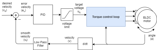
速度控制是通过在 扭矩控制环 中添加一个 PID 速度控制器来实现的。PID 控制器读取电机速度 v,将其滤波为 vf,并向扭矩控制环设置扭矩目标(uq 电压或 iq 电流),以使其达到并维持用户设定的目标速度 vd。
控制器参数
要调整此控制环,您可以设置角度 PID 控制器和速度测量低通滤波器的参数。
// controller configuration based on the control type
// velocity PID controller parameters
// default P=0.5 I = 10 D = 0
motor.PID_velocity.P = 0.2;
motor.PID_velocity.I = 20;
motor.PID_velocity.D = 0.001;
// jerk control using voltage voltage ramp
// default value is 300 volts per sec  ~ 0.3V per millisecond
motor.PID_velocity.output_ramp = 1000;

// velocity low pass filtering
// default 5ms - try different values to see what is the best.
// the lower the less filtered
motor.LPF_velocity.Tf = 0.01;

// setting the limits
// either voltage
motor.voltage_limit = 10; // Volts - default driver.voltage_limit
// of current
motor.current_limit = 2; // Amps - default 0.2Amps
PID 控制器的参数包括比例增益 P、积分增益 I、微分增益 D 和 output_ramp。
- 一般来说,提高比例增益 P 会使电机控制器反应更灵敏,但过大的 P 会导致不稳定。将其设置为 0 将禁用控制器的比例部分。
- 积分增益 I 也是如此,其值越高,电机对干扰的反应速度越快,但过大的值会导致不稳定。将其设置为 0 将禁用控制器的积分部分。
- 控制器的微分部分 D 通常最难设置,因此建议先将其设置为 0,然后调整 P 和 I。一旦调整好 P 和 I,如果出现超调,可以添加少量 D 分量来消除超调。
- output_ramp 值用于减小发送到电机的电压值的最大变化量。该值越高,PI 控制器能够更快地改变 Uq 值。该值越低,可能的变化越小,控制器的响应性越差。此参数的值设置为 “伏特 / 秒 [V/s]”,换句话说,即控制器在单位时间内可以升高的电压量。如果将 voltage_ramp 值设置为 10 V/s,并且平均而言控制环每 1ms 运行一次。那么控制器每次能够改变的 Uq 值为 10[V/s]*0.001[s] = 0.01V,这并不多。
此外,为了平滑速度测量,简易 FOC 库实现了速度低通滤波器。低通滤波器 是信号平滑的标准形式,它只有一个参数 —— 滤波时间常数 Tf。
- 值越低,滤波器的影响越小。如果将 Tf 设为 0,则基本上完全移除了滤波器。特定实现的精确 Tf 值很难预先猜测,但一般来说,Tf 的值范围会在 0 到 0.5 秒之间。
voltage_limit 参数用于在某些情况下限制可以发送到电机的电压。
为了获得最佳性能,您需要对这些参数进行一些调整。😁
有关此方法的更多理论和源代码文档,请查看 深入探究部分。
速度运动控制示例
以下是一个带有电压模式扭矩控制的速度运动控制的基本示例,包含完整配置。该程序将设置 2 RAD/s 的目标速度并保持该速度(抵抗干扰)。
#include <SimpleFOC.h>

// motor instance
BLDCMotor motor = BLDCMotor( pole_pairs , phase_resistance );
// driver instance
BLDCDriver3PWM driver = BLDCDriver3PWM(pwmA, pwmB, pwmC, enable);

// Magnetic sensor instance
MagneticSensorSPI AS5x4x = MagneticSensorSPI(chip_select, 14, 0x3FFF);

void setup() {

  // initialize magnetic sensor hardware
  AS5x4x.init();
  // link the motor to the sensor
  motor.linkSensor(&AS5x4x);

  // driver config
  driver.init();
  motor.linkDriver(&driver);

  // set motion control loop to be used
  motor.controller = MotionControlType::velocity;

  // controller configuration
  // default parameters in defaults.h

  // controller configuration based on the control type
  // velocity PID controller parameters
  // default P=0.5 I = 10 D =0
  motor.PID_velocity.P = 0.2;
  motor.PID_velocity.I = 20;
  motor.PID_velocity.D = 0.001;
  // jerk control using voltage voltage ramp
  // default value is 300 volts per sec  ~ 0.3V per millisecond
  motor.PID_velocity.output_ramp = 1000;

  // velocity low pass filtering
  // default 5ms - try different values to see what is the best.
  // the lower the less filtered
  motor.LPF_velocity.Tf = 0.01;

  // since the phase resistance is provided we set the current limit not voltage
  // default 0.2
  motor.current_limit = 1; // Amps

  // use monitoring with serial
  Serial.begin(115200);
  // comment out if not needed
  motor.useMonitoring(Serial);

  // initialize motor
  motor.init();
  // align sensor and start FOC
  motor.initFOC();

  Serial.println("Motor ready.");
  _delay(1000);
}

// velocity set point variable
float target_velocity = 2; // 2Rad/s ~ 20rpm

void loop() {
  // main FOC algorithm function
  motor.loopFOC();

  // Motion control function
  motor.move(target_velocity);
}
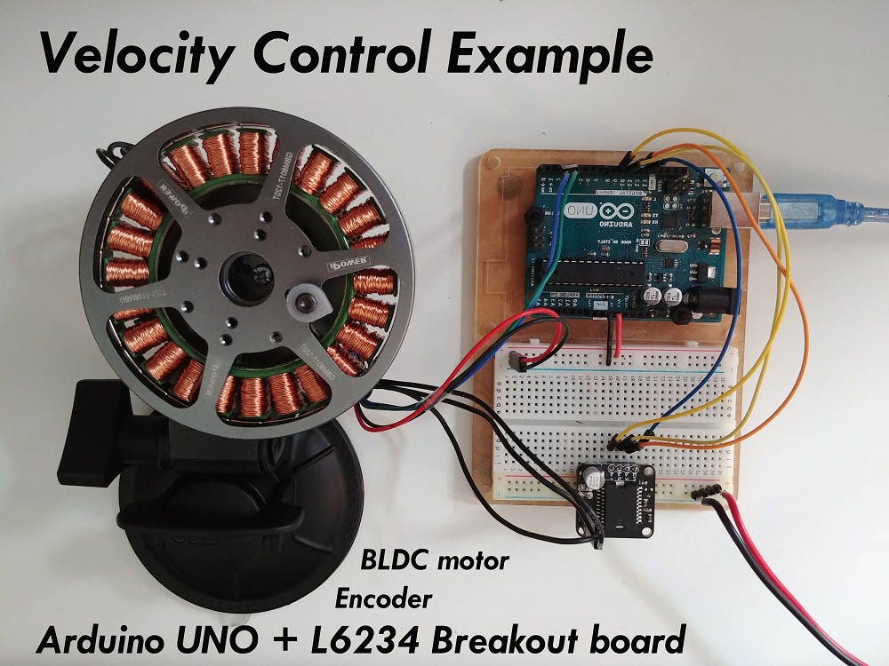
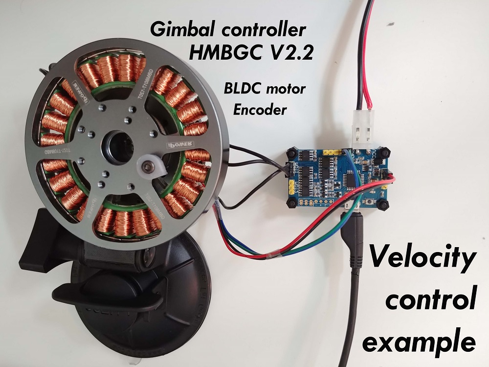
项目示例
以下是两个使用速度运动控制的项目示例,描述了所需的完整硬件 + 软件设置。
在 示例项目 部分中找到更多项目。