位置控制示例
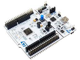
使用 简易FOC盾牌 和 Stm32 Nucleo-64
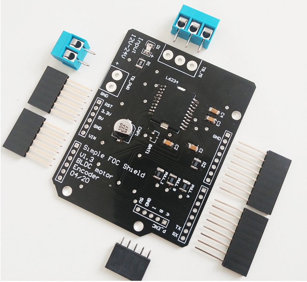
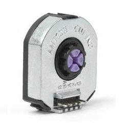
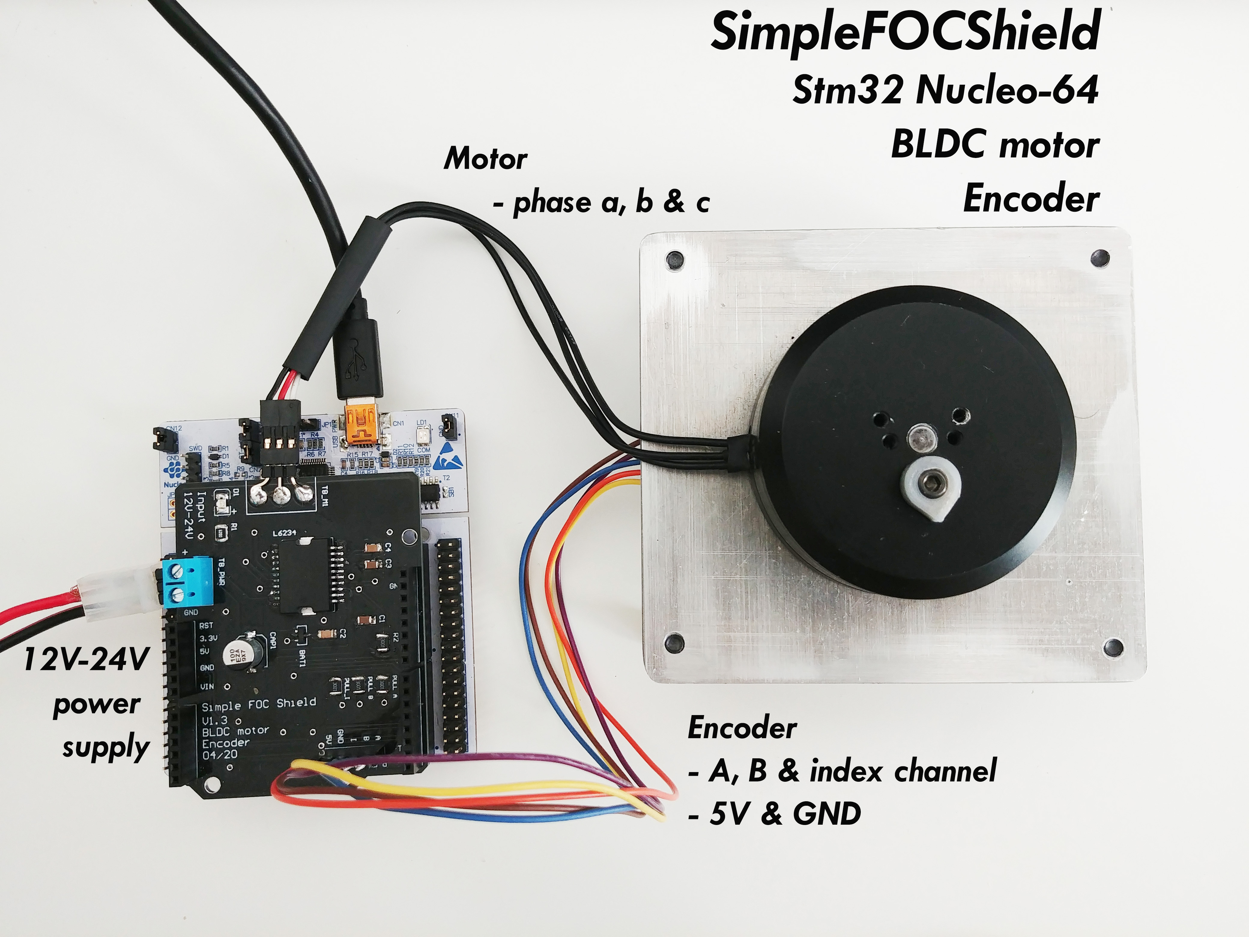
在这个 BLDC 电机位置控制示例中,我们将使用以下硬件:

连接所有设备
有关 Nucleo 板和 简易FOC盾牌 连接的更深入解释,请查看 连接示例。
有关 简易FOC盾牌 的更多信息,请查看 文档。
编码器
- 通道
A和B连接到编码器连接器P_ENC的A和B端子。 - 索引通道也可以直接连接到
P_ENC的I端子
电机
- 电机相
a、b和c直接连接到电机端子连接器TB_M1
Arduino 代码
让我们浏览这个示例的完整代码并一起编写。 首先,你需要包含 SimpleFOC 库:
#include <SimpleFOC.h>
确保你已经安装了该库。如果你还没有安装,请查看 入门页面
编码器代码
首先,我们定义具有 A 和 B 通道引脚以及每转脉冲数的 Encoder 类。
// define Encoder
Encoder encoder = Encoder(A1, A2, 2048, A0);
然后,我们定义缓冲回调函数。
// channel A, B and index callbacks
void doA(){encoder.handleA();}
void doB(){encoder.handleB();}
void doI(){encoder.handleIndex();}
在 setup() 函数中,我们初始化编码器并启用中断:
// initialize encoder hardware
encoder.init();
// hardware interrupt enable
encoder.enableInterrupts(doA, doB, doI);
就这样,让我们设置电机。
有关编码器的更多配置参数,请查看
Encoder类 文档。
电机代码
首先,我们需要定义具有极对数(11)的 BLDCMotor 类。
// define BLDC motor
BLDCMotor motor = BLDCMotor(11);
如果你不确定你的极对数是多少,请查看 find_pole_pairs.ino 示例。
接下来,我们需要定义具有电机 PWM 引脚编号和驱动器使能引脚的 BLDCDriver3PWM 类。
// define BLDC driver
BLDCDriver3PWM driver = BLDCDriver3PWM(9, 10, 11, 8);
然后在 setup() 中,如果电源电压不是 12 伏,我们首先配置电源电压并初始化驱动器。
// power supply voltage
// default 12V
driver.voltage_power_supply = 12;
driver.init();
```oltage_power_supply = 12;
接下来我们可以更改的是索引搜索速度:
// index search velocity
// default 1 rad/s
motor.velocity_index_search = 3;
然后,我们通过指定 motor.controller 变量来告诉电机运行哪个控制循环。
// set control loop type to be used
// MotionControlType::torque
// MotionControlType::velocity
// MotionControlType::angle
motor.controller = MotionControlType::angle;
现在我们配置速度 PI 控制器参数。
// velocity PI controller parameters
// default P=0.5 I = 10
motor.PID_velocity.P = 0.2;
motor.PID_velocity.I = 20;
此外,我们可以配置低通滤波器时间常数 Tf。
// velocity low pass filtering
// default 5ms - try different values to see what is the best.
// the lower the less filtered
motor.LPF_velocity.Tf = 0.01;
最后,我们配置位置 P 控制器增益和速度限制变量。
// angle P controller
// default P=20
motor.P_angle.P = 20;
//  maximal velocity of the position control
// default 20
motor.velocity_limit = 20;
有关角度控制环参数的更多信息,请查看 文档。
接下来,我们将编码器和驱动器连接到电机,进行硬件初始化和磁场定向控制的初始化。
// link the motor to the sensor
motor.linkSensor(&encoder);
// link the motor to the driver
motor.linkDriver(&driver);

// initialize motor
motor.init();
// align encoder and start FOC
motor.initFOC();

// initial target value
motor.target = 0;
当然,电机的最后一段重要代码是 loop 函数中的 FOC 程序。
void loop() {
// iterative FOC function
motor.loopFOC();

// iterative function setting and calculating the angle/position loop
// this function can be run at much lower frequency than loopFOC function
motor.move();
}
就这样,这是电机、FOC 以及运动控制初始化和配置的完整代码。现在让我们启用用户通信。
有关更多配置参数和控制循环,请查看
BLDCMotor类 文档。
监控电机初始化
为了启用它,我们需要在调用 motor.init() 和 motor.initFOC() 之前启用 监控:
Serial.begin(115200);
// enable monitoring functionality
motor.useMonitoring(Serial);
用户通信
最后,Arduino 简易FOC库 使你能够实时更改所有配置参数,以及读取电机状态变量,并通过使用 命令器接口 设置目标值。
首先,我们实例化命令器类:
Commander command = Commander(Serial);
然后我们为通用电机回调创建包装器:
void onMotor(char* cmd){ command.motor(&motor, cmd); }
我们订阅新的命令回调:
void setup(){
  ....
  command.add('M', onMotor, "motor");
  ....
}
我们将命令器运行时函数添加到 Arduino loop 中:
void loop(){
  ....
  command.run();
}
就这样,我们所有的配置都已完成并准备就绪,让我们看看完整的代码!
有关 监控 和 电机命令 的更多信息,请访问 编写代码部分。
完整的 Arduino 代码
#include <SimpleFOC.h>

// init BLDC motor
BLDCMotor motor = BLDCMotor( 11 );
// init driver
BLDCDriver3PWM driver = BLDCDriver3PWM(9, 10, 11, 8);
//  init encoder
Encoder encoder = Encoder(2, 3, 2048);
// channel A and B callbacks
void doA(){encoder.handleA();}
void doB(){encoder.handleB();}

// commander interface
Commander command = Commander(Serial);
void onMotor(char* cmd){ command.motor(&motor, cmd); }

void setup() {

  // initialize encoder hardware
  encoder.init();
  // hardware interrupt enable
  encoder.enableInterrupts(doA, doB);
  // link the motor to the sensor
  motor.linkSensor(&encoder);

  // power supply voltage
  // default 12V
  driver.voltage_power_supply = 12;
  driver.init();
  // link the motor to the driver
  motor.linkDriver(&driver);

  // index search velocity
  // default 1 rad/s
  motor.velocity_index_search = 3;

  // set control loop to be used
  motor.controller = MotionControlType::angle;

  // controller configuration based on the control type
  // velocity PI controller parameters
  // default P=0.5 I = 10
  motor.PID_velocity.P = 0.2;
  motor.PID_velocity.I = 20;
  // jerk control using voltage voltage ramp
  // default value is 300 volts per sec  ~ 0.3V per millisecond
  motor.PID_velocity.output_ramp = 1000;

  // velocity low pass filtering
  // default 5ms - try different values to see what is the best.
  // the lower the less filtered
  motor.LPF_velocity.Tf = 0.01;

  // angle P controller
  // default P=20
  motor.P_angle.P = 20;
  //  maximal velocity of the position control
  // default 20
  motor.velocity_limit = 20;

  // monitoring port
  Serial.begin(115200);
  // enable monitoring functionality
  motor.useMonitoring(Serial);

  // initialize motor
  motor.init();
  // align encoder and start FOC
  motor.initFOC();

  // initial angle target
  // it will be changed by the commander class
  motor.target = 0;

  // define the motor id
  command.add('M', onMotor, "motor");

  Serial.println("Motor ready.");
  Serial.println("Set the target angle using serial terminal:");
  _delay(1000);
}

void loop() {
  // iterative FOC function
  motor.loopFOC();

  // position motion control loop
  motor.move();

  // user communication
  command.run();
}