On this page
Torque control using DC current
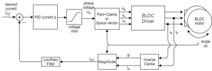
This control loop allows you to run the BLDC motor as it is a current controlled DC motor. This torque control algorithm requires current sensing hardware. The user sets the target current \(I_d\) to the FOC algorithm calculates the necessary phase voltages \(u_a\) ,\(u_b\) and \(u_c\) in order to maintain it. This mode is enabled by:
// DC current torque control mode
motor.torque_controller = TorqueControlType::dc_current;
How does it work exactly
The DC current torque control algorithm reads the phase currents of the Stepper motor (\(i_a\) and \(i_b\)). The phase currents are transformed into the currents \(i_\alpha\) and \(i_\beta\) using the Inverse Clarke transform. For example if the phase currents \(i_a\) and \(i_b\) are measured:
\[i_\alpha = i_a, \quad i_\beta =i_a\frac{1}{\sqrt{3}} + i_b\frac{2}{\sqrt{3}}\]Then we can can calculate the magnitude of the current measured at the motor as
\[i_{DC} = \sqrt{i_\alpha^2 + i_\beta^2}\]Now as this magnitude does not contain the information about direction of the current (positive or negative) we need to use the sign of the current to determine the direction of the current. The simplest way to calculate the sign of the current is using the sign of the \(i_q\) component of the current vector, which we can calculate using the Park transform using the current angle \(a\).
\[i_q = i_\beta \cos(a) - i_\alpha\sin(a)\]Finally the DC current \(i_{DC}\) is calculated as the magnitude of the current vector \(i_q\).
\[i_{DC} = \text{sign}(i_q)\cdot\sqrt{i_\alpha^2 + i_\beta^2}\]Using the target current value \(I_d\) and the measured \(i_{DC}\) the PID controller calculates the appropriate voltage \(U_q\) to be set to the motor.
\[U_q = \text{PID}(I_d - i_{DC})\]While \(U_d\) is kept in 0.
\[U_d = 0\]Finally torque control algorithm finds the appropriate voltages \(u_a\), \(u_b\) and \(u_c\) that create the calculated \(U_q\) and \(U_d\) voltages. This is done using the Park+Clarke (or SpaceVector) transformation.
Note
The assumption of this torque control mode is that the torque generated in the motor is proportional the DC current \(i_{DC}\) drawn by the motor (\(i_{DC}\) = \(i_q\)). Therefore by controlling this current we user can control the torque value. This assumption is only true for the low velocities, for higher velocities the \(i_d\) component of the current becomes higher and \(i_{DC}\)=\(i_q\) no longer holds.
Configuration parameters
In order to make this loop run smoothly the user needs to configure the PID controller parameters of teh PID_current_q and Low pass filter LPF_current_q time constant.
// PID parameters - default
motor.PID_current_q.P = 5;                       // 3    - Arduino UNO/MEGA
motor.PID_current_q.I = 1000;                    // 300  - Arduino UNO/MEGA
motor.PID_current_q.D = 0;
motor.PID_current_q.limit = motor.voltage_limit;
motor.PID_current_q.ramp = 1e6;                  // 1000 - Arduino UNO/MEGA
// Low pass filtering - default
LPF_current_q.Tf= 0.005;                         // 0.01 - Arduino UNO/MEGA
Torque control example code
A simple example of the DC current based torque control using Inline current sensor and setting the target value by serial command interface.
#include <SimpleFOC.h>
// BLDC motor & driver instance
BLDCMotor motor = BLDCMotor(11);
BLDCDriver3PWM driver = BLDCDriver3PWM(9, 5, 6, 8);
// encoder instance
Encoder encoder = Encoder(2, 3, 500);
// channel A and B callbacks
void doA(){encoder.handleA();}
void doB(){encoder.handleB();}
// current sensor
InlineCurrentSense current_sense = InlineCurrentSense(0.01, 50.0, A0, A2);
// instantiate the commander
Commander command = Commander(Serial);
void doTarget(char* cmd) { command.scalar(&motor.target, cmd); }
void setup() {
// initialize encoder sensor hardware
encoder.init();
encoder.enableInterrupts(doA, doB);
// link the motor to the sensor
motor.linkSensor(&encoder);
// driver config
// power supply voltage [V]
driver.voltage_power_supply = 12;
driver.init();
// link driver
motor.linkDriver(&driver);
// link the driver to the current sense
current_sense.linkDriver(&driver);
// current sense init hardware
current_sense.init();
// link the current sense to the motor
motor.linkCurrentSense(¤t_sense);
// set torque mode:
motor.torque_controller = TorqueControlType::dc_current;
// set motion control loop to be used
motor.controller = MotionControlType::torque;
// foc current control parameters (Arduino UNO/Mega)
motor.PID_current_q.P = 5;
motor.PID_current_q.I= 300;
motor.LPF_current_q.Tf = 0.01;
// use monitoring with serial
Serial.begin(115200);
// comment out if not needed
motor.useMonitoring(Serial);
// initialize motor
motor.init();
// align sensor and start FOC
motor.initFOC();
// add target command T
command.add('T', doTarget, "target current");
Serial.println(F("Motor ready."));
Serial.println(F("Set the target current using serial terminal:"));
_delay(1000);
}
void loop() {
// main FOC algorithm function
motor.loopFOC();
// Motion control function
motor.move();
// user communication
command.run();
}


