On this page
Velocity control loop
This control loop allows you to spin your motor with desired velocity. This mode is enabled by:
// set velocity motion control loop
motor.controller = MotionControlType::velocity;
You can find some examples in the examples/motion_control/velocity_motion_control/ library folder.
How it works
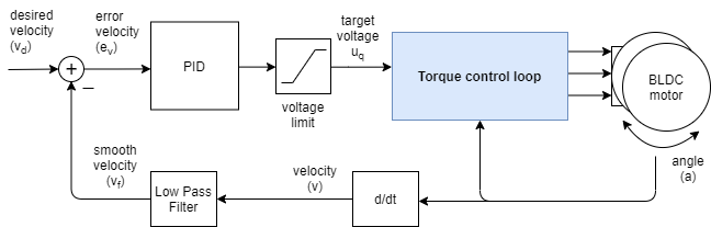
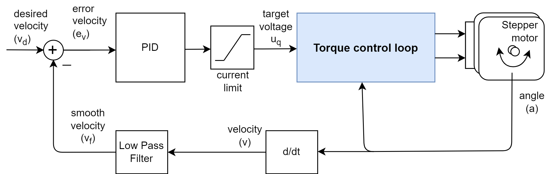
The velocity control closes the control loop around the torque control, regardless which one it is. If it is the voltage mode without phase resistance set, the velocity motion control will set the the torque command using the voltage uq:
And if it is any of the current torque control modes (FOC or DC current) or voltage mode with provided phase resistance, the velocity motion control will be setting the target current iq:

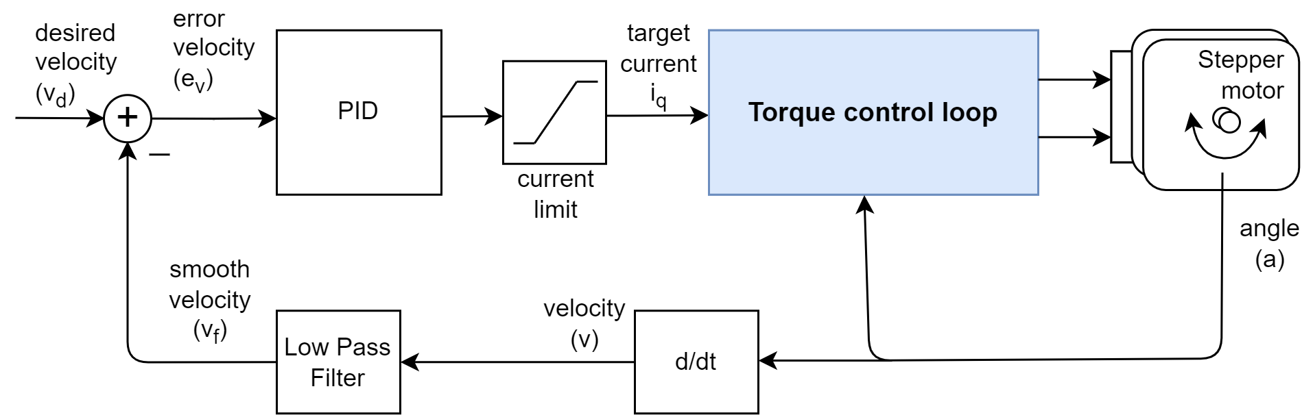
The velocity control is created by adding a PID velocity controller to the torque control loop. PID controller reads the motor velocity v, filters it to vf and sets the torque target (uq voltage or iq current) to the torque control loop in a such manner that it reaches and maintains the target velocity vd, set by the user.
Control parameters
The velocity control loop outer loop around the torque control loop, so the parameters of the torque control loop will also have an impact on the performance of the velocity control loop. So before tuning the velocity control loop, it is recommended to first tune the torque control loop.
See torque control documentation
Once you have your torque loop nice and tuned, the velocity control loop can be tuned by adjusting the PID controller and velocity measurement low pass filter. The PID controller has three key parameters: proportional gain P, integral gain I, and derivative gain D.
-
Proportional Gain (
P): IncreasingPmakes the motor controller more responsive. However, too high a value can lead to instability. SettingPto0disables this part of the controller. -
Integral Gain (
I): A higherIvalue speeds up the motor’s response to disturbances, but excessive values can also cause instability. SettingIto0disables this part. -
Derivative Gain (
D): This parameter is often the most challenging to set. It’s recommended to start withDat0, tuningPandIfirst. If overshoot occurs, gradually increaseDto mitigate it. This parameter is often not neded and can be left at0for many applications.
// velocity PID controller parameters
// default P=0.5 I = 10 D = 0
motor.PID_velocity.P = 0.2;
motor.PID_velocity.I = 20;
To smooth out velocity measurements, the Simple FOC library includes a low-pass filter. Low-pass filters are commonly used for signal smoothing and have one parameter: the filtering time constant Tf.
- Filtering Time Constant (
Tf): A lowerTfvalue means less filtering effect. SettingTfto0removes the filter entirely. The optimalTfvalue is typically between0and0.05seconds.
// velocity low pass filtering
// default 5ms - try different values to see what is the best.
// the lower the less filtered
motor.LPF_velocity.Tf = 0.01;
For optimal performance, you may need to experiment with these parameters. 😁
Go to the quick guide for tuning guide
Don't forget the torque control loop
The velocity control loop relies on the underlying torque control loop, so the parameters of the torque control loop will also have an impact on the performance of the velocity control loop. See the torque control documentation for more information about the different torque control modes and their parameters.
Additional Advanced Parameters
The PID gains and the low-pass filter time constant are the most important parameters to tune and the ones that will have the biggest impact on the performance of the velocity control loop. There are several other parameters that can be set for the velocity control loop for specific use cases, but they are not necessary for the majority of use cases and can be left at their default values.
-
Output Ramp: This parameter limits how quickly the PID controller’s output can change, helping to reduce system jerkiness. It is measured in Volts per second [V/s] or Amps per second [A/s]. For example, a setting of
1000 V/smeans the output cannot change faster than1volt per millisecond. Setting it to0disables this limit (default is0). -
Limit: This parameter restricts the PID controller’s output, measured in Volts [V] or Amps [A]. Setting it to
NOT_SETremoves the limit. This limit can be automatically set usingupdateVoltageLimit()orupdateCurrentLimit(), or manually adjusted for different limits. -
Sampling Time: This sets the PID controller’s sampling time in seconds [s]. The default is
NOT_SET, allowing the PID to calculate the sampling time based on the time between calls to thePID_velocitycontroller. Specifying a value can save processing time, but it should closely match the actual sampling time. For instance, ifmotor.move()runs at1000Hz, set the sampling time to0.001seconds.
Motion control frequency
By default, the velocity control loop runs at the same frequency \(f_{MC}\) as the torque control loop \(f_{TC}\), which is typically around 1-10 kHz. However, in some cases, you may want to run the velocity control loop at a lower frequency than the torque control loop. In that case you can use the motion_downsampling parameter of the motor.
For example, setting motion_downsampling to 10 will run the velocity control loop at 100 Hz while the torque control loop runs at 1 kHz:
motor.motion_downsampling = 10; // run velocity loop at 10 times lower frequency than torque loop
In other words, the velocity control loop will run at a frequency of \(f_{MC} = \frac{f_{TC}}{\texttt{motion_downsampling}}\), meaning that the motor.move() function will be called every motion_downsampling number of motor.loopFOC() calls.
Control Parameters Overview
| Parameter | Variable | Description | Default Value | Unit |
|---|---|---|---|---|
Proportional Gain (P) | motor.PID_velocity.P | Controls the responsiveness of the controller. Too high can cause instability. | 0.5 | \(\frac{Vs}{rad}\) or \(\frac{As}{rad}\) |
Integral Gain (I) | motor.PID_velocity.I | Speeds up response to disturbances. Excessive values can cause instability. | 10.0 | \(\frac{V}{rad}\) or \(\frac{A}{rad}\) |
Derivative Gain (D) | motor.PID_velocity.D | Helps to reduce overshoot. Recommended to start at 0. | 0.0 | \(\frac{Vs^2}{rad}\) or \(\frac{As^2}{rad}\) |
Filtering Time Constant (Tf) | motor.LPF_velocity.Tf | Determines the amount of low-pass filtering applied to velocity measurements. | 0.005 | \(s\) |
| Output Ramp | motor.PID_velocity.output_ramp | Limits how quickly the output can change. | NOT_SET | \(\frac{V}{s}\) or \(\frac{A}{s}\) |
| Limit | motor.PID_velocity.limit | Restricts the output of the PID controller. | NOT_SET | \(V\) or \(A\) |
| Sampling Time | motor.PID_velocity.sampling_time | Sets the sampling time for the PID controller. | NOT_SET | \(s\) |
| Motion downsampling | motor.motion_downsampling | Run velocity loop at lower frequency than torque loop. | 1 | - |
For more theoretical insights and source code documentation, refer to the digging deeper section.
Velocity & Torque Limits
The velocity control loop operates within two distinct sets of constraints. Understanding the difference is key to a stable system:
-
Velocity Limit (
velocity_limit): This is a hard software cap on your target. Even if you setmotor.target = 500, the controller will treat it as100if your limit is100. It prevents the motor from reaching dangerous speeds. -
Torque/Effort Limit (
voltage_limitorcurrent_limit): This defines the maximum strength the PID controller is allowed to use to reach your target.- If the torque limit is too low, the motor will struggle to reach the target velocity, especially under load, resulting in sluggish performance.
- If the torque limit is too high, the motor may become unstable and vibrate as it aggressively tries to reach the target velocity.
- Another way of looking at the torque limit is as the level of “stiffness” or “backdrivability” of the velocity control loop. A higher torque limit allows the motor to fight disturbances more effectively, making it stiffer, while a lower torque limit results in a softer response.
You can set the velocity limit and the torque limit independently in runtime:
// setting the limits
motor.updateVelocityLimit(10); // set the velocity limit to 10 Rad/s
// either voltage
motor.updateVoltageLimit(10); // Volts - default driver.voltage_limit
// or current
motor.updateCurrentLimit(2); // Amps - default 0.2Amps

// or less preferred way
motor.velocity_limit = 10; // set the velocity limit to 10 Rad/s
motor.voltage_limit = 10; // Volts - default driver.voltage_limit
motor.current_limit = 2; // Amps - default 0.2Amps
Target & Feed-forward terms
The velocity control loop in addition to the target value, allows you to add feed-forward terms to the control loop. There are 3 feed-forward terms that can be added to the velocity control loop:
| Term | Variable | Description | Unit |
|---|---|---|---|
| Target velocity | motor.target | This is the target velocity that the controller will try to achieve. It can be set by changing the target parameter of the motor. | \(\frac{rad}{s}\) |
| Velocity feed-forward | motor.feed_forward_velocity | This term adds a constant velocity to the velocity control loop. For example, it can be used to improve tracking performance for trapezoidal motion profiles. | \(\frac{rad}{s}\) |
| Current feed-forward | motor.feed_forward_current | This term adds a constant current to the torque control loop. For example, it can be used to compensate for friction or other constant loads on the motor. Only if torque control mode is current based. See the torque control section. | \(A\) |
| Voltage feed-forward | motor.feed_forward_voltage | This term adds a constant voltage to the torque control loop. For example, it can be used to compensate for back-EMF or other voltage drops in the system. Can be used if the torque control mode is voltage or current based. | \(V\) |
The target velocity can be set and modified in runtime by changing the target parameter of the motor.
motor.target = 2.0; // set target velocity to 2 Rad/s
Velocity units
The units of the
motor.targetvariable in velocity control mode are radians per second \(\frac{rad}{s}\). If you want to use different units, like RPM or degrees per second, you will need to convert them accordingly.
To set the feed-forward terms can be modified in runtime by changing the corresponding parameters of the motor.
// velocity feed-forward
motor.feed_forward_velocity = 1.0; // add 1 Rad/s to the velocity
// current feed-forward
motor.feed_forward_current.q = 0.5; // add 0.5 A to the
// voltage feed-forward
motor.feed_forward_voltage.q = 1.0; // add 1 V to the voltage
Be careful with feed-forward terms
The feed-forward terms can be very useful for improving the performance of the control loop, but they can also cause instability if not used carefully. They are intended for advanced users who have a good understanding of the system and the control loop. If you are not sure about how to use them, it is recomended not to use them.
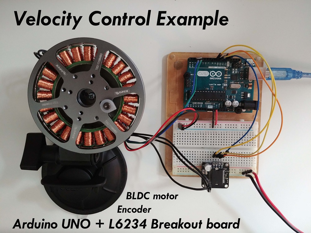
Velocity motion control example
Here is one basic example of the velocity motion control with the estimated current mode torque control with the complete configuration. The program will set the target velocity of 2 RAD/s and maintain it (resist disturbances) .
#include <SimpleFOC.h>

// motor instance
BLDCMotor motor = BLDCMotor( pole_pairs, phase_resistance, KV_rating, inductance );
// driver instance
BLDCDriver3PWM driver = BLDCDriver3PWM(pwmA, pwmB, pwmC, enable);

// Magnetic sensor instance
MagneticSensorSPI AS5x4x = MagneticSensorSPI(chip_select, 14, 0x3FFF);

void setup() {

  // initialize magnetic sensor hardware
  AS5x4x.init();
  // link the motor to the sensor
  motor.linkSensor(&AS5x4x);

  // driver config
  driver.voltage_power_supply = 12; // V
  driver.init();
  motor.linkDriver(&driver);

  // set motion control loop to be used
  motor.controller = MotionControlType::velocity;
  // set torque control mode
  motor.control_type = TorqueControlType::estimated_current;

  // velocity PID controller parameters
  // default P=0.5 I = 10 D =0
  motor.PID_velocity.P = 0.2;
  motor.PID_velocity.I = 20;

  // velocity low pass filtering
  // the lower the less filtered
  motor.LPF_velocity.Tf = 0.01;

  // set the torque limit by setting the current limit
  // default 2 A
  motor.updateCurrentLimit(1); // Amps

  // use monitoring with serial
  Serial.begin(115200);
  // comment out if not needed
  motor.useMonitoring(Serial);

  // initialize motor
  motor.init();
  // align sensor and start FOC
  motor.initFOC();

  Serial.println("Motor ready.");
  _delay(1000);
}

// velocity set point variable
float target_velocity = 2; // 2Rad/s ~ 20rpm

void loop() {
  // main FOC algorithm function
  motor.loopFOC();

  // Motion control function
  motor.move(target_velocity);
}
Project examples
Here are two project examples which use velocity motion control and describe the full hardware + software setup needed.
Find more projects in the example projects section.