On this page
Encoder setup
Step 1. Instantiate Encoder class
To initialize the encoder you need to provide the encoder A and B channel pins, encoder PPR and optionally index pin.
//  Encoder(int encA, int encB , int cpr, int index)
//  - encA, encB    - encoder A and B pins
//  - ppr           - impulses per rotation  (cpr=ppr*4)
//  - index pin     - (optional input)
Encoder encoder = Encoder(2, 3, 8192, A0);
Step 2. Configuration
When the Encoder class is instantiated, we need to configure it. First feature we can configure is enabling or disabling the Quadrature mode. If the Encoder is run in the quadrature mode its number of impulses per rotation(PPR) is quadrupled by detecting each CHANGE of the signals A and B - CPR = 4xPPR. In some applications, when the encoder PPR is high it can be too much for the Arduino to handle so it is preferable not to use Quadrature mode. By default all the encoders use Quadrature mode. If you would like to enable or disable this parameter do it in the Arduino setup() function before init() call:
// Quadrature mode enabling and disabling
//  Quadrature::ON - CPR = 4xPPR  - default
//  Quadrature::OFF - CPR = PPR
encoder.quadrature = Quadrature::OFF;
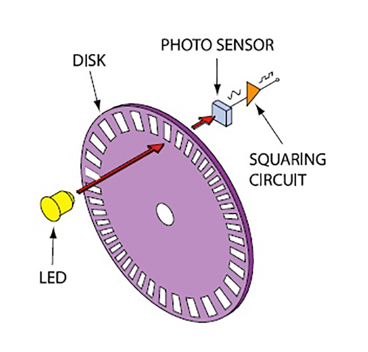
CPR, PPR?!
PPR (pulses per revolution) - this is the physical number of impulses the encoder has per revolution. CPR (counts per revolution) - this is amount you are going to have in your counter after the full rotation of the encoder. Now depending on whether you use quadrature mode (counting each edge of the impulse) or not (counting just the rising edge) you will have different CPR for the same PPR. For quadrature mode you will have CPR = 4xPPR and if not using quadrature mode you will have CPR=PPR
Additionally the encoder has one more important parameter and this is the pullup location. Many encoders require pullups and in cases when you have an encoder that needs one and you don’t have one on your hands you can use Arduino pullups. That is set by changing the value of the encoder.pullup variable. The default value is set to Pullup::USE_EXTERN but if you would like to change it to use the MCU ones do:
// check if you need internal pullups
// Pullup::USE_EXTERN - external pullup added  - default
// Pullup::USE_INTERN - needs internal arduino pullup
encoder.pullup = Pullup::USE_INTERN;
Arduino Pullup 20kΩ
Be careful when using internal pullups, Arduino has relatively high valued pullups around 20kΩ, which means that you might have some problems for higher velocities (for shorted impulse durations). Recommended pull-up values are between 1kΩ and 5kΩ.
Step 3. Encoder interrupt setup
There are two ways you can run encoders with Simple FOC library.
- Using hardware external interrupt
- Arduino UNO(ATmega328) pins
2and3 - STM32 boards any pin
- ESP32 any pin
- Arduino UNO(ATmega328) pins
- Using software pin change interrupt by using a library such as PciManager library
- Only for Arduino devices (ATmega328 and ATmega2560)
Software interrupts
Using the hardware external interrupts usually results in better and more reliable performance but software interrupts will work very well for lower velocities. Especially on boards that just don't have enough hardware interrupt pins, having this functionality basically enables FOC on these boards.
Hardware external interrupt
Arduino UNO has two hardware external interrupt pins, pin 2 and 3, Arduino Mega has 6 interrupt pins, pins 2, 3, 18, 19, 20and 2 whereas STM32 boards such as Nucleo and Bluepill can use all their digital pins as interrupt pins, which makes implementation much easier. For Arduino Uno, the encoder channels A and B will have to be connected exactly to the pisn 2 and 3, in order to use hardware interrupts.
Simple FOC Encoder class already has implemented initialization and encoder A and B channel callbacks. All you need to do is define two functions doA() and doB(), the buffering functions of encoder callback functions encoder.handleA() and encoder.handleB().
// interrupt routine initialization
void doA(){encoder.handleA();}
void doB(){encoder.handleB();}
And provide those functions to the encoder interrupt init function encoder.enableInterrupts()
// enable encoder hardware interrupts
encoder.enableInterrupts(doA, doB)
You can name the buffering functions as you wish. It is just important to provide them to the encoder.enableInterrupts() function. This procedure is a tradeoff between scalability and simplicity. This allows you to have more than one encoder connected to the same MCU. All you need to do is to instantiate new Encoder class and create new buffer functions. For example:
// encoder 1
Encoder enc1 =  Encoder(...);
void doA1(){enc1.handleA();}
void doB1(){enc1.handleB();}
// encoder 2
Encoder enc2 =  Encoder(...);
void doA2(){enc2.handleA();}
void doB2(){enc2.handleB();}

void setup(){
...
  enc1.init();
  enc1.enableInterrupts(doA1,doB1);
  enc2.init();
  enc2.enableInterrupts(doA2,doB2);
...
}
Index pin configuration
In order to read index pin efficiently Simple FOC library enables you to use the same approach as for the channels A and B. First you need to provide the Encoder class the index pin number:
Encoder encoder = Encoder(pinA, pinB, cpr, index_pin);
If you are using Arduino board such as Arduino Mega and similar and if you have more than 2 hardware interrupts you can connect your index pin to the hardware interrupt pin (example Arduino Mega pin 21). Your code will look like:
Encoder encoder =  Encoder(2,3,600,21);
// A and B interrupt routine
void doA(){encoder.handleA();}
void doB(){encoder.handleB();}
void doIndex(){encoder.handleIndex();}

void setup(){
  ...
  encoder.enableInterrupts(doA,doB,doIndex);
  ...
  }
The function enableInterrupts will handle all the initialization for you.
If you are using Arduino UNO to run this algorithm and you do not have enough hardware interrupt pins you will need to use software interrupt library such as PciManager library. Arduino UNO code for using an encoder with index can be:
Encoder encoder =  Encoder(2,3,600,A0);
// A and B interrupt routine
void doA(){encoder.handleA();}
void doB(){encoder.handleB();}
void doIndex(){encoder.handleIndex();}

// software interrupt listener for index pin
PciListenerImp listenerIndex(encoder.index_pin, doIndex);

void setup(){
  ...
  // hardware interrupts for A and B
  encoder.enableInterrupts(doA,doB);
  // software interrupt for index
  PciManager.registerListener(&listenerIndex);
  ...
  }
The same procedure can be done for pins A and B if your application makes you run out of the hardware interrupt pins. Software interrupts are very powerful and produce comparable results to the hardware interrupts especially if you have no other choice. The index pin produces one pulse per rotation, therefore it is not critical, so using software or hardware interrupts doesn’t change too much in terms of performance.
To explore better the difference in the encoder functions with both hardware and software interrupt approach please check the examples encoder_example.ino and encoder_software_interrupts_example.ino.
Software pin change interrupt
If you are not able to access your pins 2 and 3 of your Arduino UNO or if you want to use more than one encoder you will have to use the software interrupt approach. I suggest using the PciManager library.
The steps of using this library in code are very similar to hardware interrupt. The SimpleFOC Encoder class still provides you with all the callbacks A, B and Index channels but the Simple FOC library will not initialize the interrupts for you.
In order to use the PCIManager library you will need to include it in your code:
#include <PciManager.h>
#include <PciListenerImp.h>
Next step is the same as before, you will just initialize the new Encoder instance.
Encoder encoder = Encoder(10, 11, 8192);
// A and B interrupt callback buffers
void doA(){encoder.handleA();}
void doB(){encoder.handleB();}
Next you declare listeners PciListenerImp :
// encoder interrupt init
PciListenerImp listenerA(encoder.pinA, doA);
PciListenerImp listenerB(encoder.pinB, doB);
Finally, after running encoder.init() you skip the call of the encoder.enableInterrupts() and call the PCIManager library to register the interrupts for all the encoder channels.
// initialize encoder hardware
encoder.init();
// interrupt initialization
PciManager.registerListener(&listenerA);
PciManager.registerListener(&listenerB);
And that is it, it is very simple. It if you want more than one encoder, you just initialize the new class instance, create the new A and B callbacks, initialize the new listeners. Here is a quick example:
// encoder 1
Encoder enc1 =  Encoder(9, 10, 8192);
void doA1(){enc1.handleA();}
void doB1(){enc1.handleB();}
PciListenerImp listA1(enc1.pinA, doA1);
PciListenerImp listB1(enc1.pinB, doB1);

// encoder 2
Encoder enc2 =  Encoder(13, 12, 8192);
void doA2(){enc2.handleA();}
void doB2(){enc2.handleB();}
PciListenerImp listA2(enc2.pinA, doA2);
PciListenerImp listB2(enc2.pinB, doB2);

void setup(){
...
  // encoder 1
  enc1.init();
  PciManager.registerListener(&listA1);
  PciManager.registerListener(&listB1);
  // encoder 2
  enc2.init();
  PciManager.registerListener(&listA2);
  PciManager.registerListener(&listB2);
...
}
You can look into the HMBGC_example.ino example to see this code in action.
Index pin configuration
Enabling the index pin in the case of the software interrupt is very simple. You just need to provide it to the Encoder class initialization as additional parameter.
Encoder encoder = Encoder(pinA, pinB, cpr, index_pin);
Afterwards you create the same type of callback buffering function as for A and B channels and using the PCIManager tools initialize and register the listener for the index channel as for the A and B. Here is a quick example:
// class init
Encoder encoder =  Encoder(9, 10, 8192,11);
void doA(){encoder.handleA();}
void doB(){encoder.handleB();}
void doIndex(){encoder.handleIndex();}
// listeners init
PciListenerImp listenerA(encoder.pinA, doA);
PciListenerImp listenerB(encoder.pinB, doB);
PciListenerImp listenerIndex(encoder.index_pin, doIndex);

void setup(){
...
  // enable the hardware
  enc1.init();
  // enable interrupt
  PciManager.registerListener(&listenerA);
  PciManager.registerListener(&listenerB);
  PciManager.registerListener(&listenerIndex);
...
}
Step 4. Using encoder in real-time
There are two ways to use encoders implemented within this library:
- As motor position sensor for FOC algorithm
- As standalone position sensor
Position sensor for FOC algorithm
To use the encoder sensor with the foc algorithm implemented in this library, once when you have initialized encoder.init() it and enabled interrupts encoder.enableInterrupts(...) you just have to link it to the BLDC motor by executing:
motor.linkSensor(&encoder);
And you will be able to access the angle and velocity of the motor using the motor instance:
motor.shaft_angle; // motor angle
motor.shaft_velocity; // motor velocity
or through the sensor instance:
encoder.getAngle(); // motor angle
encoder.getVelocity(); // motor velocity
Standalone sensor
To get the encoder angle and velocity at any given time you can use the public methods:
class Encoder{
 public:
    // shaft velocity getter
    float getVelocity();
	  // shaft angle getter
    float getAngle();
}
Calling
getVelocitymultiple timesWhen calling
getVelocityit will only calculate the velocity if the elapsed time from the previous call is longer than the time specified in teh variablemin_elapsed_time(default 100us). If the elapsed time from the last call is shorter thanmin_elapsed_timethe function will return previously calculated value. Variablemin_elapsed_timecan be changed easily if necessary:encoder.min_elapsed_time = 0.0001; // 100us by default
Example code
Hardware interrupts Software interrupts
Here is a quick example using hardware interrupts:
#include <SimpleFOC.h>

Encoder encoder = Encoder(2, 3, 8192);
// interrupt routine initialization
void doA(){encoder.handleA();}
void doB(){encoder.handleB();}

void setup() {
  // monitoring port
  Serial.begin(115200);

  // enable/disable quadrature mode
  encoder.quadrature = Quadrature::ON;

  // check if you need internal pullups
  encoder.pullup = Pullup::USE_EXTERN;

  // initialize encoder hardware
  encoder.init();
  // hardware interrupt enable
  encoder.enableInterrupts(doA, doB);

  Serial.println("Encoder ready");
  _delay(1000);
}

void loop() {
  // IMPORTANT - call as frequently as possible
  // update the sensor values
  encoder.update();
  // display the angle and the angular velocity to the terminal
  Serial.print(encoder.getAngle());
  Serial.print("\t");
  Serial.println(encoder.getVelocity());
}