On this page
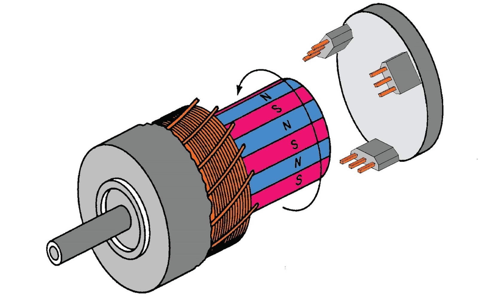
Hall sensors setup
Step 1. Instantiate HallSensor class
To initialize the hall sensors you need to provide the pin numbers for A, B and C (sometimes called U,V andW) channel and the number of pole pairs pp of the motor.
// Hall sensor instance
// HallSensor(int hallA, int hallB , int hallC , int pp)
//  - hallA, hallB, hallC    - HallSensor A, B and C pins
//  - pp                     - pole pairs
HallSensor sensor = HallSensor(2, 3, 4, 11);
Step 2. Configuration
Additionally the hall senso has one more optional parameter you may set, the pullup location. Hall sensors usually require pullups and in cases when your sensor needs one and you don’t have one on your hands you can use Arduino pullups. That is set by changing the value of the sensor.pullup variable. The default value is set to Pullup::USE_EXTERN but if you would like to change it to use the MCU ones do:
// use internal pullups
sensor.pullup = Pullup::USE_INTERN;
Arduino Pullup 20kΩ
Be careful when using internal pullups, Arduino has relatively high valued pullups around 20kΩ, which means that you might have some problems for higher velocities (for shorted impulse durations). Recommended pull-up values are in between 1kΩ and 5kΩ.
Step 2.1 Velocity outlier removal
From the release v2.2.3 HallSensor class implements the outlier removal for its velocity calculations. It is based on a simple principle where all the calculated velocities higher than a certain maximal expected velocity are considered to be an outlier. To modify the maximal expected motor velocity, you can modify the variable velocity_max. This variable is set to 1000rad/s by default which is a good starting point for most applications. Except if you are using very high performance motors, then 1000 rad/s (~10,000 rpm) could still be reachable by the motor in which case please increase this value to a number outside the motor’s reach.
// maximal expected velocity
sensor.velocity_max = 1000; // 1000rad/s by default ~10,000 rpm
Step 3. Interrupt setup (optional)
From the release v2.3.4 the HallSensor class does no longer require interrupt based operation. The interrupt based operation is still available and might be more performant in certain applications, but it is no longer required. If you are not using interrupts you can skip this step and go directly to Step 4. Using hall sensors in real-time.
There are two ways you can run hall sensors using interrupts with SimpleFOClibrary:
- Using hardware external interrupt
- Arduino UNO(ATmega328) pins
2and3 - STM32 boards any pin
- ESP32 any pin
- Teensy any pin …
- Arduino UNO(ATmega328) pins
- Using software pin change interrupt by using a library such as PciManager library
- Only for Arduino devices (ATmega328 and ATmega2560)
Software interrupts
Using the hardware external interrupts usually results in better and more reliable performance but software interrupts will work very well for lower velocities. Especially on boards that just don't have enough hardware interrupt pins, having this functionality basically enables FOC on these boards.
RULE OF THUMB: Hardware/Software or No interrupts?
- Start with the no interrupts and see if the performance is good enough for your application.
- If the performance is not good enough and if you have enough hardware interrupt pins, try using hardware interrupts.
- Otherwise, if you are using Arduino boards, try using software interrupts. (worst performance solution to be expected)
Hardware external interrupt
Arduino UNO has two hardware external interrupt pins, pin 2 and 3, Arduino Mega has 6 interrupt pins, pins 2, 3, 18, 19, 20and 2 whereas ESP32 and STM32 boards can use all their digital pins as interrupt pins, which makes implementation much easier.
Simple FOC HallSensor class already has implemented initialization and sensor A, B and C channel callbacks. All you need to do is define two functions doA(), doB() and doC(), the buffering functions of sensor callback functions sensor.handleA(), sensor.handleB() and sensor.handleC().
// interrupt routine initialization
void doA(){sensor.handleA();}
void doB(){sensor.handleB();}
void doC(){sensor.handleC();}
And provide those functions to the hall sensor interrupt init function sensor.enableInterrupts()
// enable hall sensor hardware interrupts
sensor.enableInterrupts(doA, doB, doC)
You can name the buffering functions as you wish. It is just important to provide them to the sensor.enableInterrupts() function. This procedure is a tradeoff in between scalability and simplicity. This allows you to have more than one sensor connected to the same MCU. All you need to do is to instantiate new HallSensor class and create new buffer functions. For example:
// sensor 1
HallSensor sensor1 = HallSensor(...);
void doA1(){sensor1.handleA();}
void doB1(){sensor1.handleB();}
void doC1(){sensor1.handleC();}
// sensor 2
HallSensor sensor2 = HallSensor(...);
void doA2(){sensor2.handleA();}
void doB2(){sensor2.handleB();}
void doC2(){sensor2.handleC();}

void setup(){
...
  sensor1.init();
  sensor1.enableInterrupts(doA1,doB1,doC1);
  sensor2.init();
  sensor2.enableInterrupts(doA2,doB2,doC2);
...
}
Software pin change interrupt
For Arduino UNO and other boards using ATmega328 chips, we will have to use the software interrupt library to use Hall senors with this library, because we will need three interrupt pins and ATmega328 has only 2.
I suggest using the PciManager library.
The steps of using this library in code are very similar to hardware interrupt. The SimpleFOC HallSensor class still provides you with all the callbacks A, B and C channels but the Simple FOC library will not initialize the interrupts for you.
In order to use the PCIManager library you will need to include it in your code:
#include <PciManager.h>
#include <PciListenerImp.h>
Next step is the same as before, you will just initialize the new HallSensor instance.
HallSensor sensor = HallSensor(2, 3, 4, 11);
// A, B and C interrupt callback buffers
void doA(){sensor.handleA();}
void doB(){sensor.handleB();}
void doC(){sensor.handleC();}
Then you declare listeners PciListenerImp :
// sensor interrupt init
PciListenerImp listenA(sensor.pinA, doA);
PciListenerImp listenB(sensor.pinB, doB);
PciListenerImp listenC(sensor.pinC, doC);
Finally, after running sensor.init() you skip the call of the sensor.enableInterrupts() and call the PCIManager library to register the interrupts for all the sensor channels.
// initialize sensor hardware
sensor.init();
// interrupt initialization
PciManager.registerListener(&listenA);
PciManager.registerListener(&listenB);
PciManager.registerListener(&listenC);
And that is it, it is very simple. It if you want more than one sensor, you just initialize the new class instance, create the new A, B and C callbacks, initialize the new listeners. Here is a quick example:
// sensor 1
HallSensor sensor1 = HallSensor(2, 3, 4, 11);
void doA1(){sensor1.handleA();}
void doB1(){sensor1.handleB();}
void doC1(){sensor1.handleC();}
PciListenerImp listenC1(sensor1.pinC, doC1);

// sensor 2
HallSensor sensor2 = HallSensor(5, 6, 7, 11);
void doA2(){sensor2.handleA();}
void doB2(){sensor2.handleB();}
void doC2(){sensor2.handleC();}
PciListenerImp listenA2(sensor2.pinA, doA2);
PciListenerImp listenB2(sensor2.pinB, doB2);
PciListenerImp listenC2(sensor2.pinC, doC2);

void setup(){
...
  // sensor 1
  sensor1.init();
  sensor1.enableInterrupts(doA1,doB1); // two hardware interrupts
  PciManager.registerListener(&listenC1); // one software interrupt

  // sensor 2
  sensor2.init();
  PciManager.registerListener(&listenA2);
  PciManager.registerListener(&listenB2);
  PciManager.registerListener(&listenC2);
...
}
Step 4. Using hall sensors in real-time
There are two ways to use hall sensor implemented within this library:
- As motor position sensor for FOC algorithm
- As standalone position sensor
Position sensor for FOC algorithm
To use the hall sensor with the foc algorithm implemented in this library, once when you have initialized sensor.init() it and enabled interrupts sensor.enableInterrupts(...) you just have to link it to the BLDC motor by executing:
motor.linkSensor(&sensor);
And you will be able to access the angle and velocity of the motor using the motor instance:
motor.shaft_angle; // motor angle
motor.shaft_velocity; // motor velocity
or through the sensor instance:
sensor.getAngle(); // motor angle
sensor.getVelocity(); // motor velocity
Example code
Without interrupts Hardware interrupts Software interrupts
Here is a quick example hall sensor code without interrupts:
#include <SimpleFOC.h>

// Motor instance
BLDCMotor motor = BLDCMotor(11);
// driver instance
BLDCDriver3PWM driver = BLDCDriver3PWM(9, 5, 6, 10);

// Hall sensor instance
// HallSensor(int hallA, int hallB , int hallC , int pp)
//  - hallA, hallB, hallC    - HallSensor A, B and C pins
//  - pp                     - pole pairs
HallSensor sensor = HallSensor(2, 3, 4, 11);

void setup() {
  // monitoring port
  Serial.begin(115200);

  // driver config
  driver.init();
  motor.linkDriver(&driver);

  // initialize sensor hardware
  sensor.init();
  // link the motor and the sensor
  motor.linkSensor(&sensor);

  // enable motor
  motor.init();
  // align sensor and start FOC
  motor.initFOC();

  Serial.println("Sensor ready");
  _delay(1000);
}

void loop() {
  // FOC algorithm function
  motor.loopFOC();

  // motion control
  motor.move();
}
Standalone sensor
To get the hall sensor angle and velocity at any given time you can use the public methods:
class HallSensor{
 public:
    // shaft velocity getter
    float getVelocity();
	  // shaft angle getter
    float getAngle();
}
Calling
getVelocitymultiple timesWhen calling
getVelocityit will only calculate the velocity if the elapsed time from the previous call is longer than the time specified in teh variablemin_elapsed_time(default 100us). If the elapsed time from the last call is shorter thanmin_elapsed_timethe function will return previously calculated value. Variablemin_elapsed_timecan be changed easily if necessary:sensor.min_elapsed_time = 0.0001; // 100us by default
Example Code
Without interrupts Hardware interrupts Software interrupts
Here is a quick example hall sensor code without interrupts:
#include <SimpleFOC.h>

// Hall sensor instance
// HallSensor(int hallA, int hallB , int hallC , int pp)
//  - hallA, hallB, hallC    - HallSensor A, B and C pins
//  - pp                     - pole pairs
HallSensor sensor = HallSensor(2, 3, 4, 11);

void setup() {
  // monitoring port
  Serial.begin(115200);

  // initialize sensor hardware
  sensor.init();

  Serial.println("Sensor ready");
  _delay(1000);
}

void loop() {
  // IMPORTANT - call as frequently as possible
  // update the sensor values
  sensor.update();
  // display the angle and the angular velocity to the terminal
  Serial.print(sensor.getAngle());
  Serial.print("\t");
  Serial.println(sensor.getVelocity());
}