On this page
Position control example
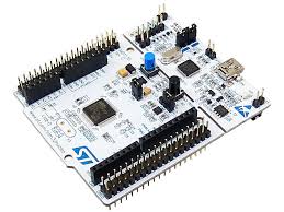
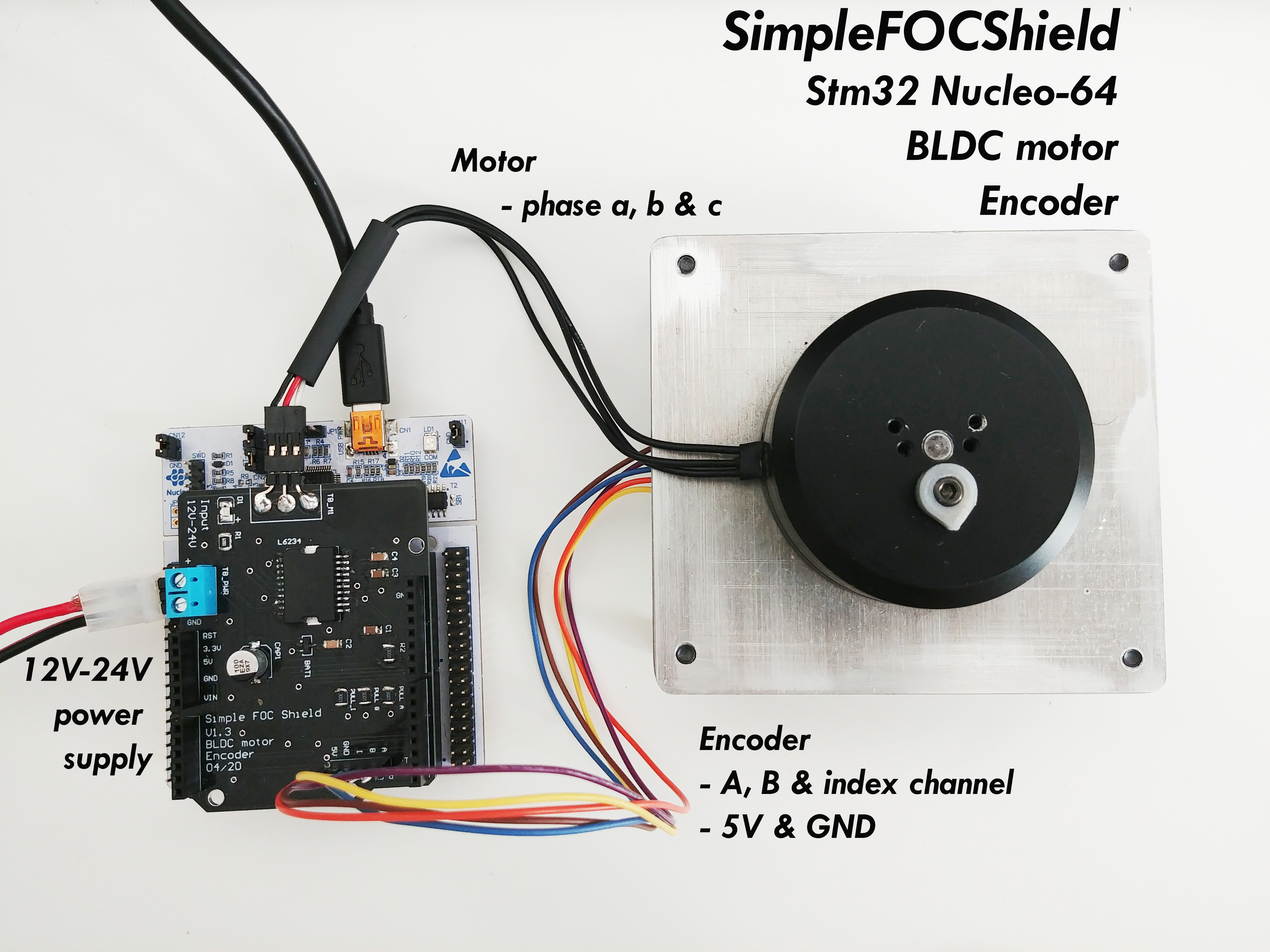
using SimpleFOCShield and Stm32 Nucleo-64
For this BLDC motor position control example we are going to be using this hardware:
Connecting everything together
For a bit more in depth explanation of how to connect Nucleo board and SimpleFOCShield connection please check the connection examples.
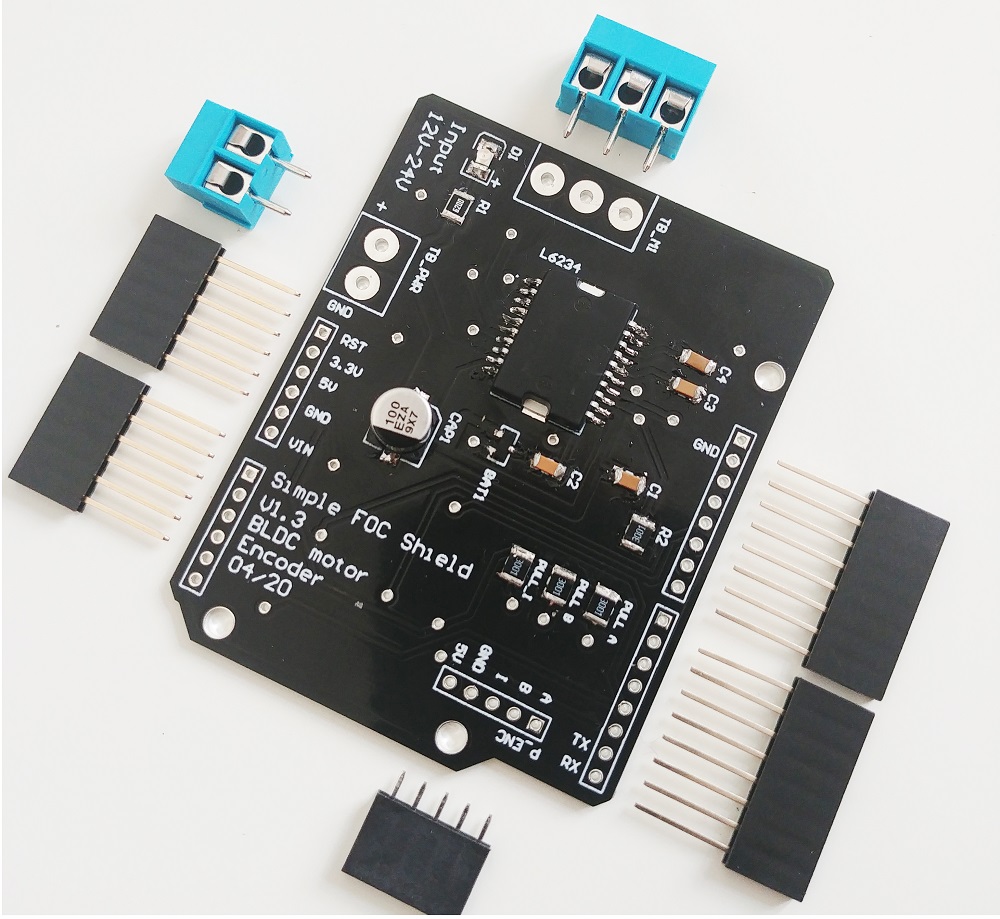
For more information about the SimpleFOCShield check the docs.
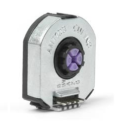
Encoder
- Channels
AandBare connected to the encoder connectorP_ENC, terminalsAandB. - Index channel you can connect directly to the
P_ENCas well to the terminalIMotor
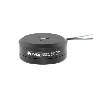
- Motor phases
a,bandcare connected directly the motor terminal connectorTB_M1
Arduino code
Let’s go through the full code for this example and write it together. First thing you need to do is include the SimpleFOC library:
#include <SimpleFOC.h>
Make sure you have the library installed. If you still don’t have it please check the get started page
Encoder code
First we define the Encoder class with the A and B channel pins and number of impulses per revolution.
// define Encoder
Encoder encoder = Encoder(A1, A2, 2048, A0);
Then we define the buffering callback functions.
// channel A, B and index callbacks
void doA(){encoder.handleA();}
void doB(){encoder.handleB();}
void doI(){encoder.handleIndex();}
In the setup() function we initialize the encoder and enable interrupts:
// initialize encoder hardware
encoder.init();
// hardware interrupt enable
encoder.enableInterrupts(doA, doB, doI);
And that is it, let’s setup the motor.
For more configuration parameters of the encoders please check the Encoder class docs. Motor code
First we need to define the BLDCMotor class with the number of pole pairs (11)
// define BLDC motor
BLDCMotor motor = BLDCMotor(11);
If you are not sure what your pole pairs number is please check the find_pole_pairs.ino example. Next we need to define the BLDCDriver3PWM class with the PWM pin numbers of the motor and the driver enable pin
// define BLDC driver
BLDCDriver3PWM driver = BLDCDriver3PWM(9, 10, 11, 8);
Then in the setup() we configure first the voltage of the power supply if it is not 12 Volts and init the driver.
// power supply voltage
// default 12V
driver.voltage_power_supply = 12;
driver.init();
```oltage_power_supply = 12;
Next thing we can change is the index search velocity:
// index search velocity
// default 1 rad/s
motor.velocity_index_search = 3;
Then we tell the motor which control loop to run by specifying the motor.controller variable.
// set control loop type to be used
// MotionControlType::torque
// MotionControlType::velocity
// MotionControlType::angle
motor.controller = MotionControlType::angle;
Now we configure the velocity PI controller parameters
// velocity PI controller parameters
// default P=0.5 I = 10
motor.PID_velocity.P = 0.2;
motor.PID_velocity.I = 20;
Additionally we can configure the Low pass filter time constant Tf
// velocity low pass filtering
// default 5ms - try different values to see what is the best.
// the lower the less filtered
motor.LPF_velocity.Tf = 0.01;
Finally we configure position P controller gain and the velocity limit variable.
// angle P controller
// default P=20
motor.P_angle.P = 20;
//  maximal velocity of the position control
// default 20
motor.velocity_limit = 20;
For more information about the angle control loop parameters please check the doc.
Next we connect the encoder and the driver to the motor, do the hardware init and init of the Field Oriented Control.
// link the motor to the sensor
motor.linkSensor(&encoder);
// link the motor to the driver
motor.linkDriver(&driver);

// initialize motor
motor.init();
// align encoder and start FOC
motor.initFOC();

// initial target value
motor.target = 0;
The last peace of code important for the motor is of course the FOC routine in the loop function.
void loop() {
// iterative FOC function
motor.loopFOC();

// iterative function setting and calculating the angle/position loop
// this function can be run at much lower frequency than loopFOC function
motor.move();
}
That is it, that is the full code for the motor, FOC and motion control initialization and configuration. Let’s enable user communication now.
For more configuration parameters and control loops please check the BLDCMotor class doc. Monitor motor init
In order to enable it we need to enable monitoring before the call of the motor.init() and motor.initFOC():
Serial.begin(115200);
// enable monitoring functionality
motor.useMonitoring(Serial);
User communication
At the end the Arduino SimpleFOClibrary enables you to change all the configuration parameters in real-time as well as read the motor state variables, and set the target values by using commander interface.
First we instantiate the commander class:
Commander command = Commander(Serial);
Then we create the wrapper for generic motor callback:
void onMotor(char* cmd){ command.motor(&motor, cmd); }
We subscribe the new command callback:
void setup(){
  ....
  command.add('M', onMotor, "motor");
  ....
}
And we add the commander runtime function the Arduino loop:
void loop(){
  ....
  command.run();
}
And that is it, we everything configured and ready to go, let’s see the full code!
For more info about the monitoring and motor commands visit the Writing the Code section.
Full Arduino code
#include <SimpleFOC.h>

// init BLDC motor
BLDCMotor motor = BLDCMotor( 11 );
// init driver
BLDCDriver3PWM driver = BLDCDriver3PWM(9, 10, 11, 8);
//  init encoder
Encoder encoder = Encoder(2, 3, 2048);
// channel A and B callbacks
void doA(){encoder.handleA();}
void doB(){encoder.handleB();}

// commander interface
Commander command = Commander(Serial);
void onMotor(char* cmd){ command.motor(&motor, cmd); }

void setup() {

  // initialize encoder hardware
  encoder.init();
  // hardware interrupt enable
  encoder.enableInterrupts(doA, doB);
  // link the motor to the sensor
  motor.linkSensor(&encoder);

  // power supply voltage
  // default 12V
  driver.voltage_power_supply = 12;
  driver.init();
  // link the motor to the driver
  motor.linkDriver(&driver);

  // index search velocity
  // default 1 rad/s
  motor.velocity_index_search = 3;

  // set control loop to be used
  motor.controller = MotionControlType::angle;

  // controller configuration based on the control type
  // velocity PI controller parameters
  // default P=0.5 I = 10
  motor.PID_velocity.P = 0.2;
  motor.PID_velocity.I = 20;
  // jerk control using voltage voltage ramp
  // default value is 300 volts per sec  ~ 0.3V per millisecond
  motor.PID_velocity.output_ramp = 1000;

  // velocity low pass filtering
  // default 5ms - try different values to see what is the best.
  // the lower the less filtered
  motor.LPF_velocity.Tf = 0.01;

  // angle P controller
  // default P=20
  motor.P_angle.P = 20;
  //  maximal velocity of the position control
  // default 20
  motor.velocity_limit = 20;

  // monitoring port
  Serial.begin(115200);
  // enable monitoring functionality
  motor.useMonitoring(Serial);

  // initialize motor
  motor.init();
  // align encoder and start FOC
  motor.initFOC();

  // initial angle target
  // it will be changed by the commander class
  motor.target = 0;

  // define the motor id
  command.add('M', onMotor, "motor");

  Serial.println("Motor ready.");
  Serial.println("Set the target angle using serial terminal:");
  _delay(1000);
}

void loop() {
  // iterative FOC function
  motor.loopFOC();

  // position motion control loop
  motor.move();

  // user communication
  command.run();
}