On this page
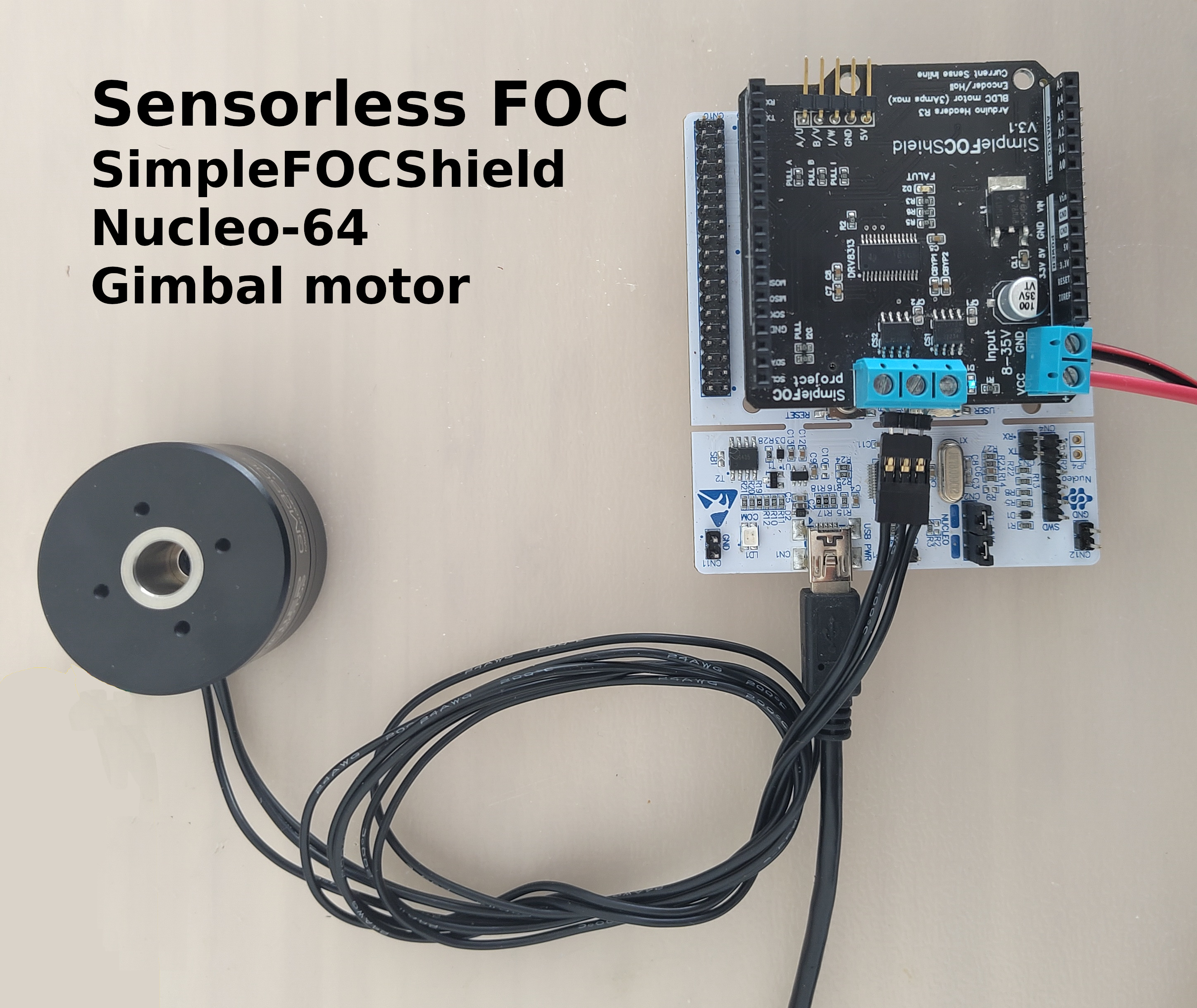
Sensorless FOC example
using SimpleFOCShield and Stm32 Nucleo-64
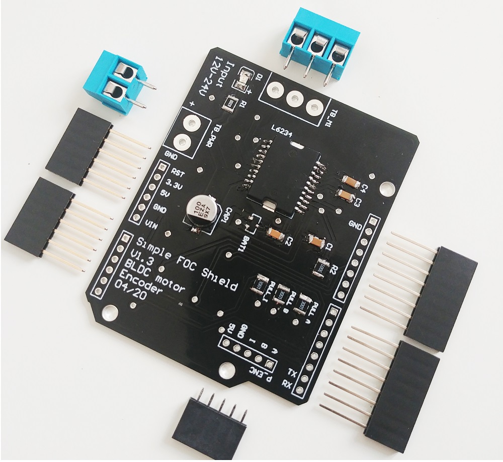
For this example of the Sensorless FOC control we are going to be using this hardware:
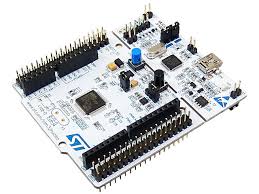

This is just an example of how to use the SimpleFOClibrary to control a motor without any sensors. You can use any other motor (BLDC, stepper or hybrid stepper) and any other driver or microcontroller. As long as the driver has enough current capacity to drive the motor and the microcontroller has enough processing power to run the FOC algorithm, you can use it. The only real constraint is that you need to be able to measure the phase current of the motor. This is because the sensorless observer uses the phase current to estimate the rotor position and velocity.
Connecting everything together
For a bit more in depth explanation of how to connect Nucleo board and SimpleFOCShield connection please check the connection examples.
For more information about the SimpleFOCShield check the docs.
Motor
- Motor phases
a,bandcare connected directly the motor terminal connectorTB_M1
SimpleFOCShield connections
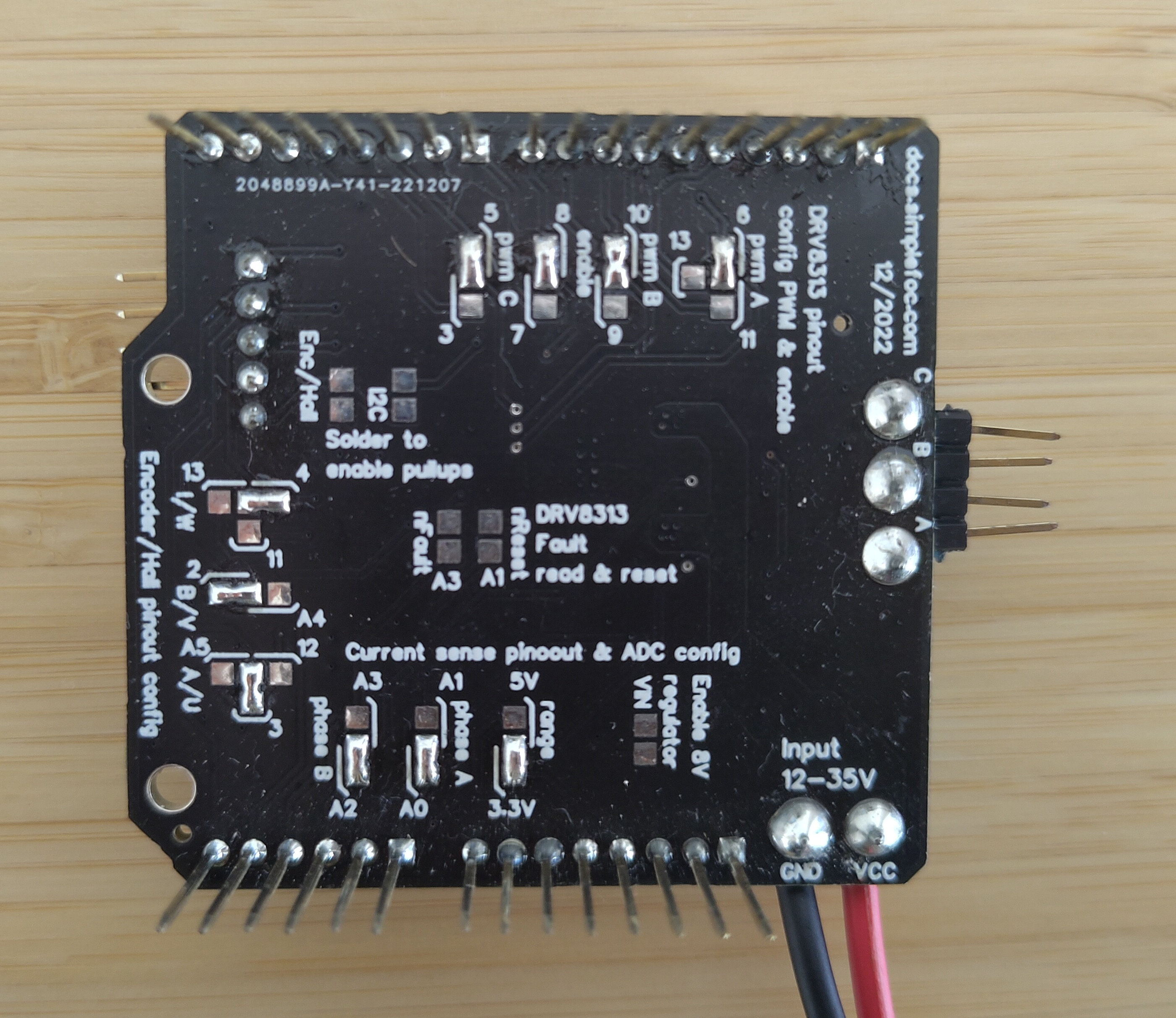
| Signal | Pwm A | Pwm B | Pwm C | Enable |
|---|---|---|---|---|
| Pin | 6 | 10 | 5 | 8 |
Arduino code
First thing you need to do is include the SimpleFOC library:
#include <SimpleFOC.h>
Make sure you have the library installed. If you still don’t have it please check the get started page
Then import the drivers library and the Sensorless observer:
#include <SimpleFOCDrivers.h>
#include "encoders/MXLEMMING_observer/MXLEMMINGObserverSensor.h"
Motor and driver
Next we need to define the BLDC motor and driver classes. The motor class is used to control the motor and the driver class is used to control the power electronics.
// define BLDC motor
// - 11 is the number of pole pairs
// - 5.9 is the resistance of the motor [Ohms]
// - 100 is the KV rating of the motor in [RPM per Volt]
// - 0.0005 is the phase inductance [H]
// These parameters are specific to the motor you are using, please check the motor datasheet
// I'm using GBM3506-120T
BLDCMotor motor = BLDCMotor(11, 5.94, 100, 0.0005);

// define BLDC driver
BLDCDriver3PWM driver = BLDCDriver3PWM(6, 10, 5, 8);
Note: Correct motor parameters are crucial!
Having the correct motor parameters is crucial for the motor to work properly.
KV rating
Motor’s KV rating is usually easy to find in the datasheets. If the datasheet does not specify the KV rating, they often specify some rated voltage and speed. In that case you can calculate the KV by dividing the motor’s RPM by the voltage applied to it. You can also use the
examples/utils/calibration/find_kv_rating.inoexample to find it out.
Phase resistance and inductance
If you are not sure what your motor resistance and inductance are, you can use this code to measure them:
#include <SimpleFOC.h> // Stepper motor & BLDC driver instance BLDCMotor motor = BLDCMotor(11); // SimpleFOCShield BLDCDriver3PWM driver = BLDCDriver3PWM(6, 10, 5, 8); // inline current sensor instance // ACS712-05B has the resolution of 0.185mV per Amp LowsideCurrentSense current_sense = LowsideCurrentSense(185.0f, A0, A2); void setup() { // use monitoring with serial Serial.begin(115200); // enable more verbose output for debugging // comment out if not needed SimpleFOCDebug::enable(&Serial); // driver config // power supply voltage [V] driver.voltage_power_supply = 20; driver.init(); // link driver motor.linkDriver(&driver); // link current sense and the driver current_sense.linkDriver(&driver); // current sense init and linking current_sense.init(); motor.linkCurrentSense(¤t_sense); // initialise motor motor.init(); // find the motor parameters motor.characteriseMotor(3.5f); _delay(1000); } void loop() { // do nothing _delay(1000); }The code output will look like this:
MOT: Init
MOT: Enable driver.
MOT: Measuring phase to phase resistance, keep motor still...
MOT: Estimated phase to phase resistance: 5.94
MOT: Measuring inductance, keep motor still...
MOT: Inductance measurement complete!
MOT: Measured D-inductance in mH: 0.50
MOT: Measured Q-inductance in mH: 0.59
So then you can use the measured values to define the motor:
// define BLDC motor
// - 11 is the number of pole pairs
// - 5.94 is the resistance of the motor [Ohms]
// - 100 is the KV rating of the motor in [RPM per Volt]
// - 0.0005 is the phase inductance [H]
BLDCMotor motor = BLDCMotor(11, 5.94, 100, 0.0005);
Sensorless observer
Next we need to define the sensorless observer class. The observer is used to estimate the rotor position and velocity without using any sensors. The observer is based on the MXLEMMING_observer
// define sensorless observer
MXLEMMINGObserverSensor observer = MXLEMMINGObserverSensor(motor);
And you’re more or less set, the rest of the code is the same as usual.
Full Arduino code
The full code for the sensorless FOC example is as follows:
#include <SimpleFOC.h>
#include <SimpleFOCDrivers.h>
#include "encoders/MXLEMMING_observer/MXLEMMINGObserverSensor.h"
// Stepper motor & BLDC driver instance
BLDCMotor motor = BLDCMotor(11, 5.94, 100, 0.0005);
// SimpleFOCShield
BLDCDriver3PWM driver = BLDCDriver3PWM(6, 10, 5, 8);
// MXLEMMING observer sensor instance
MXLEMMINGObserverSensor observer = MXLEMMINGObserverSensor(motor);
// inline current sensor instance
// ACS712-05B has the resolution of 0.185mV per Amp
LowsideCurrentSense current_sense = LowsideCurrentSense(185.0f, A0, A2);
// commander communication instance
Commander command = Commander(Serial);
void doMotor(char* cmd){ command.motor(&motor, cmd); }
void setup() {
// use monitoring with serial
Serial.begin(115200);
// enable more verbose output for debugging
// comment out if not needed
SimpleFOCDebug::enable(&Serial);
// link the motor to the sensor
motor.linkSensor(&observer);
// driver config
// power supply voltage [V]
driver.voltage_power_supply = 20;
driver.init();
// link driver
motor.linkDriver(&driver);
// link current sense and the driver
current_sense.linkDriver(&driver);
// set control loop type to be used
motor.controller = MotionControlType::torque;
motor.torque_controller = TorqueControlType::foc_current;
// current sense init and linking
current_sense.init();
motor.linkCurrentSense(¤t_sense);
// initialise motor
motor.init();
// skip the sensor alignment
motor.sensor_direction= Direction::CW;
motor.zero_electric_angle = 0;
motor.initFOC();
// subscribe motor to the commander
command.add('M', doMotor, "motor");
// Run user commands to configure and the motor (find the full command list in docs.simplefoc.com)
Serial.println("Motor ready.");
_delay(1000);
}
void loop() {
// iterative setting FOC phase voltage
motor.loopFOC();
// iterative function setting the outter loop target
motor.move();
// motor monitoring
motor.monitor();
// user communication
command.run();
}
And you can interact with the motor using the commander. For example, you can set the target torque by sending the command M0.5 to set the target torque to 0.5Amps. You can also use other commands to control the motor, like M0 to stop the motor, M1 to set the target torque to 1Amp, etc. You can find the full command list in the docs.