On this page
This page has been extracted from the SimpleFOC Community forum
Motor and sensor alignment procedure
The motor and sensor alignment procedure is a crucial part of motor control. It is the procedure that is used to find the difference between the electrical angle of the motor and the angle of the sensor. This is a very important step because it is the first step in motor control and it has to be done correctly in order for BLDC or Stepper motor to be able to move at all. 😃
Basic principles of the BLDC
Every BLDC motor has windings in its stator and permanent magnets in its rotor. Here is a quick graphic of a very simple 1 pole pair motor. This motor has three phases and each phase has one pair windings.
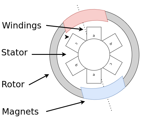
When current is passed through the winding coils, a magnetic field is induced in the windings with a polarity depending on the current polarity. In my figures I am going to simplify this effect and draw the coils in color red/blue - north/south as if they were magnets.
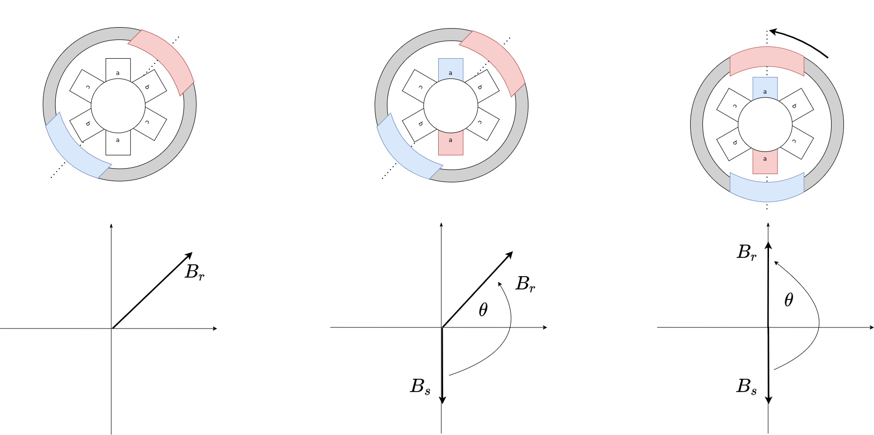
So whenever current flows through the motor coils, a magnetic field is generated and the motor’s rotor will try to align with the coils’ magnetic field. Here is an example of the motor behavior for two different initial positions by applying current in the phase a

From the graphic, and what’s intuitive, you can see that regardless of the rotor’s initial position, when you set a certain magnetic field in the stator windings the motor will always try to align with that magnetic field, and in a case of this simple motor it will always come to the same position.
Definition of the field vectors
Now when talking about how to align different magnetic fields, it is usual to introduce the field vectors. What does it mean in practice and how do we characterise the force that actually makes the rotor move? The magnetic field vector shows the strength of the magnetic field by its length and its direction will be determined going from the north to south pole. It is very simple, here is a quick visualisation:

Now when we defined the vectors of the magnetic field based on the motor’s physics, the force that turns the rotor of the motor depends on the strength of the two magnetic fields ( \(B_r\) - strength of rotor’s permanent magnets and \(B_s\) - strength of the field in the coils produced by the current \(I\)) and fields and the angle in between them
\[F \sim B_r\cdot B_s\cdot sin(\theta)\]or
\[F \sim B_r\cdot I\cdot sin(\theta)\]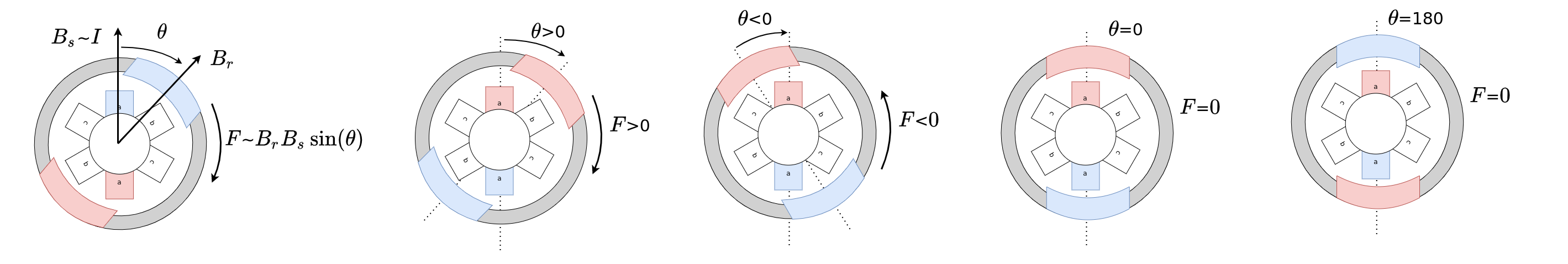
This relationship means that the motor’s torque will be directly proportional to the two magnetic fields but also to the sine of the angle between them. As we cannot control the magnetic field of the rotor’s magnets, we will have to control the strength and orientation of the magnetic field vector of the stator windings (field oriented control).
Control of the field vector orientation (FOC)
From the force equation we can see that we can see that in order to use maximally our current and produce the maximal force we need to keep the angle in between the two vectors at 90 degrees, because \(sin(90) = 1\). In that case the force pushing the rotor to move ( creating the motor’s torque) will be proportional only to the current \(I\) and \(B_r\)
\[F \sim B_r\cdot I\]Now to be able to keep the angle in between two magnetic fields fixed we first find the rotor’s angle in every time-step and then using this value we calculate what are the phase a,b and c currents necessary to produce a the magnetic field vector \(B_s\) that is exactly 90 degrees behind the rotor. In order to do that we use Park and Clarke transformations. We could go much deeper in this topic, if you’d be interested I’ll take some time to explain how we go from the vectors \(B_r\) and \(B_s\) and the angle \(\theta\) to the d and q coordinate system.
But the main takeaway is the that the d axis is exactly aligned with the \(B_r\) and the q axis is 90 degrees from the \(B_r\). If we take the force equation and apply the current\(I_d\) in d axis we get the magnetic field vectors \(B_s\) and \(B_r\) that are aligned
And in the q axis, we get the magnetic field vectors that have exactly 90 degree offset:
Which means if the d axis and q axis are defined in this way that any current applied in the d axis will not produce any force to move the rotor or in other words any motor torque.
However, it is possible that in some implementations of the FOC some authors choose to defined q axis as the one aligned to the \(B_r\) and d axis as 90 degrees apart from the \(B_r\) and in that case \(I_q\) does not generate any torque.
6-Step example
One simpler variant of bldc motor control is trapezoidal control (or six-step) that is used very frequently in the ESCs; It can only turn on and off the motor phases and cannot finely tune the orientation of the magnetic field vector of the stator \(B_s\). This is how it works for a half of the electrical rotation.

As you can see the idea is very similar to field oriented control but the angle in between the vectors is not always kept at 90 degrees as we do using FOC.
SimpleFOClibrary init procedure theory
In the init procedure we are searching to find the difference between the 0 angle to the position sensor we are using and the electrical 0 angle of our motor which is usually defined by the magnetic field vector of the phase a. As shown on the second image and on the one below we could set the stator’s magnetic field orientation to -180 degrees and we will be sure that the motor will always align to the 0 electric angle.
Then we can just read the sensor value and add 90 degrees to it and use it as our target position to set out stator magnetic field vector \(B_s\) to.
As we will be always adding 90 degrees to our sensor angles, in literature, many approaches (park + clarke) are defined not for the actual rotor position but for the rotor angle+90 degrees. instead of searching for the relationship between the position sensor angle and the electric angle 0, we often search for electric angle 90. In order to force the rotor to go to 90 degrees, you need to apply the 90-180 = -90 or 270 degrees.
Here is an example:

Or: 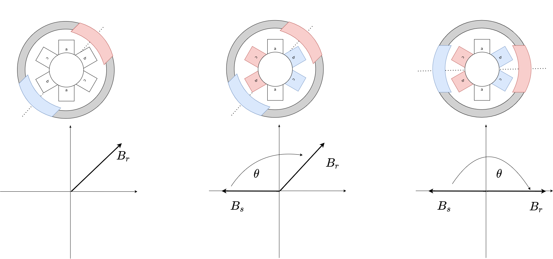
Remembering the offset between the position sensor angle and the rotor’s electrical 90 degrees angle avoids the need for adding the 90 degrees in the formulas, at least for the sinusoidal modulation. But the approaches of finding the 0 or 90 degree angles are equivalent, it’s a choice of implementation.
Limitations SimpleFOClibrary’s alignment procedure
This is a standard procedure, and probably one of the most simple ones. But there are certainly limitations. The biggest downside is, it can happen that the rotor, due to some physical imperfections, (or sometimes just friction) does not go exactly to 90 degrees but some angle close to it. Since we are only performing one measurement, we will not know that this angle is incorrect. So in that case the force generated by the motor will be less efficient because we will not be able to maintain \(sin(90) = 1\). This could be avoided by taking multiple measurements and doing some averaging or some more fancy statistics.
The other downside of course is that if we do the calibration only once at the init, we are absolutely unaware if something happens during the operation of the motor. If the sensor drifts, it could be possible to account for the change in the alignment, but at the moment we do not implement such a feature.