On this page
In-line current sensing
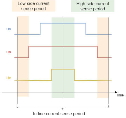
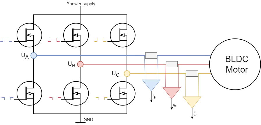
Inline current sensing technique is the simplest one to use and the most precise one. The shunt resistors are placed in-line with motor phases and the current measured on these shunt resistors will be motor phase current regardless of the state of the PWM duty cycle. This implementation is therefore very suitable for Arduino devices due to the fact that adc can be sampled at any time to read the current and the adc acquisition duration is not as important as for the other current sensing approaches. The downside of this approach is the hardware, this current sensing architecture requires high-precision bidirectional amplifiers with much better PWM rejection than the regular low-side or high-side amplifiers.
Current sensing support per MCU architecture
In-line current sensing is currently supported for almost all MCU architectures supported by the SimpleFOClibrary. The only not supported architecture is the ESP8266 which does not have 2 ADC pins, making it unable to run FOC.
| MCU | In-line Current sensing |
|---|---|
| Arduino (8-bit) | ✔️ |
| Arduino DUE | ✔️ |
| STM32 | ✔️ |
| STM32 B_G431B_ESC1 | ✔️ |
| ESP32 | ✔️ |
| ESP8266 | ❌ |
| SAMD21 | ✔️ |
| SAMD51 | ✔️ |
| Teensy | ✔️ |
| Raspberry Pi Pico | ✔️ |
| Portenta H7 | ✔️ |
| Renesas (UNO R4) | ❌ (TBD) |
| Arduino Nano Matter(📢NEW) | ✔️ |
Hardware configuration
To instantiate the inline current sensor using the SimpleFOClibrary just create an instance of the class InlineCurrentSense.
// InlineCurrentSensor constructor
//  - shunt_resistor  - shunt resistor value
//  - gain  - current-sense op-amp gain
//  - phA   - A phase adc pin
//  - phB   - B phase adc pin
//  - phC   - C phase adc pin (optional)
InlineCurrentSense current_sense  = InlineCurrentSense(0.01f, 20.0f, A0, A1, A2);
This class takes as a parameter either shunt resistance value shunt_resistor, amplification gain gain and two or three ADC channel pins depending on the available measuring hardware that you might have. It is important to specify right adc channels for right driver/motor phase. So if your pin A0 measures the phase current A and pin A1 measures the phase current B make sure to provide them to the constructor in that order.
📢 Here is a quick guide to choosing appropriate ADC pins for different MCU architectures see in docs.
Alternatively InlineCurrentSense can be created by specifying the mV per Amp ratio mVpA, more common with hall sensor based current sense like ACS712.
// InlineCurrentSensor constructor
//  - mVpA  - mV per Amp ratio
//  - phA   - A phase adc pin
//  - phB   - B phase adc pin
//  - phC   - C phase adc pin (optional)
InlineCurrentSense current_sense  = InlineCurrentSense(66.0f,  A0, A1, A2);
Measuring 2 out of 3 currents
Field Oriented Control algorithm can run with both 2 or 3 phase current measurements. If measuring 2 out of 3 currents, when defining your InlineCurrentSense class put the flag _NC (not connected) to the phase value you are not using.
For example if measuring the current on phases A (analog pin A0) and C (analog pin A1) and not measuring the current on the phase B, then you’ll define your current sense class as:
// InlineCurrentSensor constructor
InlineCurrentSense current_sense  = InlineCurrentSense(shunt_resistor, gain, A0, _NC, A1);
Some more examples:
// InlineCurrentSensor constructor
InlineCurrentSense current_sense  = InlineCurrentSense(shunt_resistor, gain, _NC, A0, A1); // when measuring B and C phase currents and not measuring A

// InlineCurrentSensor constructor
InlineCurrentSense current_sense  = InlineCurrentSense(shunt_resistor, gain, A0, A1, _NC); // when measuring A and B phase currents and not measuring C
// or
InlineCurrentSense current_sense  = InlineCurrentSense(shunt_resistor, gain, A0, A1); // when measuring A and B phase currents and not measuring C
Custom gains
The constructor of the InlineCurrentSense class only allows you to specify one shunt resistor value and one amplification gain. If your hardware configuration has different shunt/amp values for different phases you can specify them by changing the gain_x attribute:
// default values of per phase gains
current_sense.gain_a = 1.0 / shunt_resistor / gain;
current_sense.gain_b = 1.0 / shunt_resistor / gain;
current_sense.gain_c = 1.0 / shunt_resistor / gain;
For example, Arduino SimpleFOCShield v2 has the phase B of the current sensing inverted. So in its case you can specify:
// inverse current sensing gain on phase b
current_sense.gain_b *= -1;
Initialising the current sense
Once the current sense has been created it can be initialised. This init() function configures the ADC hardware for reading and finds the zero offsets of the ADC for each channel.
// init current sense
current_sense.init();
Init function is responsible for
- configuring ADC for current sensing
- calibration - offset removal
If for some reason the ADC configuration fails this function will return 0 if everything went well the function will return 1. So we suggest you to check if the init function was executed successfully before continuing:
// init current sense
if (current_sense.init())  Serial.println("Current sense init success!");
else{
  Serial.println("Current sense init failed!");
  return;
}
Once when your current sense has been intialised and calibrated you can start measuring the currents!
Enable debugging output
If you wish to see a more verbose debugging output of the current sense configuration during the current_sense.init() and see more details about the configuration and possible errors, you can use the SimpleFOCDebug class. In order to enable the verbose debugging mode make sure to enable debugging before the current_sense.init() call, preferably at the top of the setup() function.
Serial.begin(115200); // to output the debug information to the serial
SimpleFOCDebug::enable(&Serial);
See more in the SimpleFOCDebug documentation.
📢 We strongly advise to use the debugging mode when starting with the SimpleFOClibrary. It provides much more information than the standard monitoring output and can help troubleshooting potentially problems, even MCU architecture specific ones.
Using the current sense with FOC algorithm
To use the InlineCurrentSense with the FOC algorithm, first thing you’ll need to do is to associate (link) your current sense with the BLDCDriver:
BLCDriverXPWM driver = BLCDriverXPWM(...);
...
InlineCurrentSense current_sense  = InlineCurrentSense(...);

void setup(){
  ...
  // init driver
  driver.init();
  // link current sense and driver
  current_sense.linkDriver(&driver);
  ...
  current_sense.init();
  ...
}
Current sense will be using driver parameters for different synchronisation and calibration procedures.
API change - SimpleFOClibrary v2.2.2
Driver linking to the current sense is introduced from the library version v2.2.2 in order to propagate different hardware specific parameters in between ADC and PWM timers needed for advanced synchronisation for current sensing.
Once the driver is linked to the current sense, last step is to link the current sense with the motor you wish to use it with:
// link motor and current sense
motor.linkCurrentSense(¤t_sense);
Where to place the current_sense configuration in your FOC code?
It is very important that the the current sensing init function is called after the driver.init function is called. Which will make sure that the driver is configured when current sense calibration is taking place and that the valid configuration of the driver is available. Also, it is crucial that the the current sense init function is called before starting the foc algorithm with the initFOC function. Finally, we suggest to put the current sense init between the motor.init() and motor.initFOC() functions, in order to make sure that the driver is enabled during the current sense init (bit this is not mandatory). This is the suggested code structure:
void loop(){
....
// driver init
driver.init();
// link the driver to the current sense
current_sense.linkDriver(&driver);
....
// motor init
motor.init();
....
// init current sense
current_sense.init();
// link the current sense to the motor
motor.linkCurrentSense(¤t_sense);
...
// start the FOC
motor.initFOC();
}
Function initFOC() will make sure that the driver and current_sense classes are both aligned, it is very important that the phase A of the current sense is exactly the phase A of the driver etc. To verify this, the initFOC will be calling the current sense’s funciton current_sense.driverAlign(...).
Alignment with the driver phases driverAlign(...)
The current sense and the driver alignment inside initFOC is done by calling the function:
current_sense.driverAlign(voltage_sensor_align);
This function will be using the driver instance (linked to the current sense with current_sense.linkDriver(&driver)) to apply the voltage (voltage can be set using the parameter motor.voltage_sensor_align) to each of the phases and checks if the measured currents correspond to the directions of the applied voltages. This alignment procedure is able to correct for:
- Incorrect order of adc pins
- Incorrect gain sign
If monitoring is enabled for the motor during the initFOC the monitor will display the alignment status:
0- fail1- success and nothing changed2- success but pins reconfigured3- success but gains inverted4- success but pins reconfigured and gains inverted
If you are sure in your configuration and if you wish to skip the alignment procedure you can specify set the skip_align flag before calling motor.initFOC():
// skip alignment procedure
current_sense.skip_align = true;
For example, Arduino SimpleFOCShield v2, you would have a code similar to this:
// one possible combination of current sensing pins for SimpleFOCShield v2
// shunt - 10milliOhm
// gain - 50 V/V
InlineCurrentSense current_sense = InlineCurrentSense(0.01, 50.0, A0, A2);
voi loop(){
....
// driver init
driver.init();
// link the driver to the current sense
current_sense.linkDriver(&driver);
....
// motor init
motor.init();
....
// init current sense
current_sense.init();
// link the current sense to the motor
motor.linkCurrentSense(¤t_sense);
...
// invert phase b gain
current_sense.gain_b *=-1;
// skip alignment
current_sense.skip_align = true;
...
// start the FOC
motor.initFOC();
}
Standalone current sense
To use your inline current sensor as a stand-alone sensor after you have configured the hardware and calibrated it you can read the phase currents by calling:
PhaseCurrent_s current = current_sense.getPhaseCurrents();
This function returns the PhaseCurrent_s structure that which has three variables a, b and c. So you can print them out for example;
Serial.println(current.a);
Serial.println(current.b);
Serial.println(current.c); // 0 if only two currents mode
If you are using only two phase current measurements in your InlineCurrentSense, it will return the third current current.c equal to 0.
Sometimes the phase currents are hard to interpret, therefore this current sense class enables you to read the transformed current vector magnitude. The absolute DC current the motor is drawing.
float current_mag = current_sense.getDCCurrent();
Futhermore if you have an access to the position sensor of the motor connected to the driver you can get signed value of the DC current the motor is drawing by providing it to the getDCCurrent method.
float current = current_sense.getDCCurrent(motor_electrical_angle);
Finally if you have the access to the motor position sensor you current sense class will be able to tell you the FOC currents D and Q that your motor is drawing.
DQCurrent_s current = current_sense.getFOCCurrents(motor_electrical_angle);
This function returns the DQCurrent_s structure which has two variables, d and q. You can print them out for example:
Serial.println(current.d);
Serial.println(current.q);
Example code
Here is a simple example of a inline current sense as a stand-alone sensor using the SimpleFOClibrary and SimpleFOCShield v2.
#include <SimpleFOC.h>

// current sensor
// shunt resistor value
// gain value
// pins phase A,B
InlineCurrentSense current_sense = InlineCurrentSense(0.01f, 50.0f, A0, A2);

void setup() {
  // initialise the current sensing
  current_sense.init();

  // for SimpleFOCShield v2.01/v2.0.2
  current_sense.gain_b *= -1;

  Serial.begin(115200);
  Serial.println("Current sense ready.");
}

void loop() {

    PhaseCurrent_s currents = current_sense.getPhaseCurrents();
    float current_magnitude = current_sense.getDCCurrent();

    Serial.print(currents.a*1000); // milli Amps
    Serial.print("\t");
    Serial.print(currents.b*1000); // milli Amps
    Serial.print("\t");
    Serial.print(currents.c*1000); // milli Amps
    Serial.print("\t");
    Serial.println(current_magnitude*1000); // milli Amps
}