On this page
Connecting the hardware
Connecting the Arduino SimpleFOCShield to the microcontroller, BLDC motor, power-supply and the sensors is very straight forward.
Microcontroller
- Arduino SimpleFOCShield is designed to be easily stackable on all the devices featuring arduino headers, such as: Arudino UNO, Arudino MEGA, Stm32 Nucleo and similar.
- Bit it can also be used as a standalone BLDC driver as shown in combination with Stm32 Bluepill.
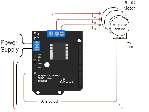
BLDC motor
- Motor phases
a,bandcare connected directly the motor terminal connectorTB_M1
BEWARE: Power limitations
Arduino SimpleFOCShield is designed for gimbal motors with internal resistance higher than R>10Ohm. The absolute maximal current of this board is 5A. Please make sure when using this board in your projects that the BLDC motor used does comply with these limits.
If you still want to use this driver with the BLDC motors with very low resistance R < 1Ohm make sure to limit the voltage set to the board.
For a bit more information about the choice of motors visit BLDC motor docs
Power supply
- Power supply cables are connected directly to the terminal
TB_PWR - Recommended power supply voltage is from 12V to 24V but in general, the board has not been tested for higher voltages, but there shouldn’t be too much problems up to 30V.
Encoder
- Channels
AandBare connected to the encoder connectorP_ENC, terminalsAandB. - If your encoder has
indexsignal you can connect it to the encoder connector as well, terminalI.

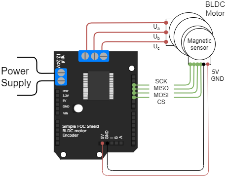
Magnetic sensor SPI
- Magnetic sensor’s SPI interface signals
SCK,MISOandMOSIare connected to the Arduino’sSPIpins (Arduino UNO13,12and11).- If the application requires more than one sensor all of them are connected to the same pins of the Arduino.
- The
chip selectpin is connected to the desired pin. Each sensor connected to the same Arduino has to have unique chip select pin.
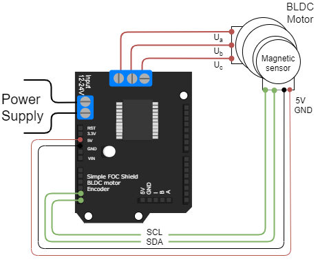
Magnetic sensor I2C
- Magnetic sensor’s I2C interface signals
SCLandSDAare connected to the Arduino’sI2Cpins (Arduino UNOA4andA5).- If the application requires more than one sensor all of them are connected to the same pins of the Arduino.
- It is possible that you will need to use additional pull-up resistors for the
SDAandSCLlines.
Magnetic sensor Analog output
- Magnetic sensor’s Analog output is connected directly to any analog input pin, on a figure below we use
A0- If the application requires more than one sensor each of them is connected to one of the analog input pins.
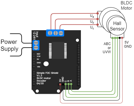
Hall sensors
- Channels
A,BandC(U,VandW) are connected to the encoder connectorP_ENC.