Reaction Wheel Inverted Pendulum project
using SimpleFOCShield
This is a project of designing and controlling the reaction wheel inverted pendulum based entirely on Arduino SimpleFOC library and SimpleFOC shield.


This is a very fun project in many ways, and it is intended:
- Students in search for a good testing platform for their advanced algorithms
- Everyone with a bit of free time and a motivation to create something cool :D
YouTube demonstration video 😃
But for me, the most exciting part of this project was the ability to use the Field Oriented Control algorithm.
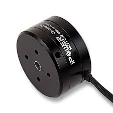
The main benefits of using the BLDC motor in this project are:
- High torque to weight ratio
- The lighter the better
- Lots of torque for low angular velocities
- No need to spin the motor to very high RPM to achieve high torques
- No gearboxes and backlash
- Very smooth operation = very stable pendulum
So far, FOC has been restricted to high-end applications due to the complexity and the cost of the hardware mostly, but also due to the lack of user-friendly, well documented software. Therefore I am very happy to show you the projects like this one, which directly benefit the FOC algorithm and BLDC motors and encourage you to use these techniques in your projects as well.
What are the necessary components?

Due to the using of the brushless motor and the SimpleFOCShield, this might be one of the simplest hardware setups of the reaction wheel inverted pendulum there is.

Please check the github repository of this project for more details about the 3d printed components and hardware.
Connecting all the components
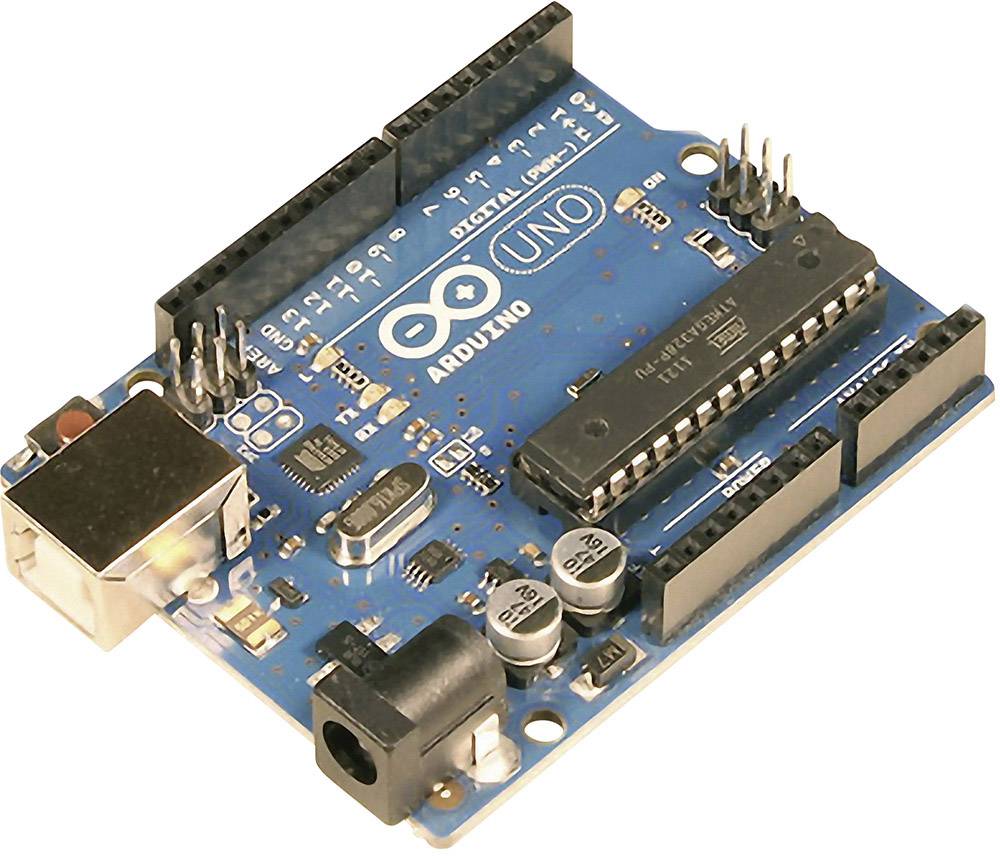
Apart from few 3d printed components, few screws and bearings for this project you will need these components:
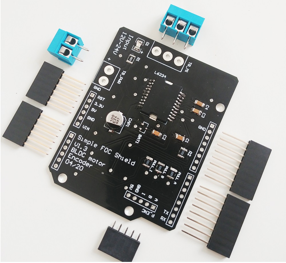
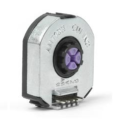
Encoder 1 (motor)
- Channels
AandBare connected to the encoder connectorP_ENC, terminalsAandB.
Encoder 2 (pendulum)
Pinout restriction
Arduino UNO doesn't have enough hardware interrupt pins for two encoders therefore we need to use the software interrupt library.
- Encoder channels
AandBare connected to the pinsA0andA1.
Motor
- Motor phases
a,bandcare connected directly the motor terminal connectorTB_M1
Arduino code
Let’s go through the full code for this project and write it together. First thing you need to do is include the SimpleFOC library:
#include <SimpleFOC.h>
Make sure you have the library installed. If you still don’t have it please check the get started page.
Also in this case, we are using two encoders so we will need to have a software interrupt library. I would suggest using PciManager library. If you have not installed it yet, you can do it using the Arduino library manager directly. Please check the Encoder class docs for more info. So once you have it please include it to the sketch:
// software interrupt library
#include <PciManager.h>
#include <PciListenerImp.h>
Encoder 1 (motor) code
First we define the Encoder class with the A and B channel pins and number of impulses per revolution.
// define Encoder
Encoder encoder = Encoder(2, 3, 500);
Then we define the buffering callback functions.
// channel A and B callbacks
void doA(){encoder.handleA();}
void doB(){encoder.handleB();}
In the setup() function we initialize the encoder and enable interrupts:
// initialize encoder hardware
encoder.init();
// hardware interrupt enable
encoder.enableInterrupts(doA, doB);
And that is it, let’s setup the pendulum encoder.
For more configuration parameters of the encoders please check the Encoder class docs. Encoder 2 (pendulum) code
We define the pendulum as the Encoder class with the A and B channel pins and number of impulses per revolution.
// define Encoder
Encoder pendulum = Encoder(A0, A1, 1000);
Then we define the buffering callback functions.
// channel A and B callbacks
void doPA(){pendulum.handleA();}
void doPB(){pendulum.handleB();}
Next we define the PciManager pin change listeners:
// pin change listeners
PciListenerImp listenerPA(pendulum.pinA, doPA);
PciListenerImp listenerPB(pendulum.pinB, doPB);
In the setup() function first we initialize the pendulum encoder:
// initialize encoder hardware
pendulum.init();
And then instead of calling pendulum.enableInterrupt() function we use the PciManager library interface to attach the interrupts.
// interrupt initialization
PciManager.registerListener(&listenerPA);
PciManager.registerListener(&listenerPB);
And that is it the pendulum is ready, let’s setup the motor.
Motor code
First we need to define the BLDCMotor class with the number of pole pairs(11).
// define BLDC motor
BLDCMotor motor = BLDCMotor(11);
If you are not sure what your pole pairs number is please check the find_pole_pairs.ino example. Next we need to define the BLDCDriver3PWM class with the PWM pin numbers and the driver enable pin.
// define BLDC driver
BLDCDriver3PWM driver  = BLDCDriver3PWM(9, 10, 11, 8);
Then in the setup() we configure first the voltage of the power supply if it is not 12 Volts and intialise the driver.
// power supply voltage
// default 12V
driver.voltage_power_supply = 12;
driver.init();
Then we tell the motor which control loop to run by specifying the motor.controller variable.
// set control loop type to be used
motor.controller = MotionControlType::torque;
For more information about the voltage control loop please check the doc.
Next we connect the encoder and driver to the motor, do the hardware init and init of the Field Oriented Control.
// link the motor to the sensor
motor.linkSensor(&encoder);
// link the motor to the driver
motor.linkDriver(&driver);

// initialize motor
motor.init();
// align encoder and start FOC
motor.initFOC();
The last peace of code important for the motor is of course the FOC routine in the loop function.
void loop() {
// iterative FOC function
motor.loopFOC();

// iterative function setting and calculating the angle/position loop
// this function can be run at much lower frequency than loopFOC function
motor.move(target_voltage);
}
Now we are able to read the two encoders and set the voltage to the motor, now we need to write the stabilization algorithm.
For more configuration parameters and control loops please check the BLDCMotor class doc. Control algorithm code
The control algorithm is divided in two stages. Stabilization and swing-up.
Stabilization
In order to stabilize the pendulum we will be using a state space controller which means that it takes in consideration all three variables important for this pendulum system:
- pendulum angle -
p_angle - pendulum velocity -
p_vel - motor velocity -
m_vel
The controller code is very simple at the end, it just calculates the linear control rule:
target_voltage = 40*p_angle + 7*p_vel + 0.3*m_vel;
The gains 40,7 and 0.3 you can imagine as weights, which tell how much we care about these variables. The highest weight is obviously on the pendulum angle and the smallest is on motor velocity that makes sense. Basically if we set 0 to the motor velocity weight, your pendulum will still be stable but your motor will probably never stop spinning. It will always have some velocity. On the other hand if you put it much higher, you will probably prioritize your motor movements over the stability and your pendulum will no longer be stable. So there is a tradeoff here.
This is a very simple explanation of a relatively complex topic and I would like to point you toward a nice youtube video explanation of similar approaches.
Also maybe interesting to say is that for a system like this one there is really no need to run it with the sample times less then 20ms. In my case I have run it at ~25ms, but you can go even to 50ms.
NOTE
The FOC algorithmmotor.loopFOC()will run ~1ms but the control algorithm and the functionmotor.move()will be downsampled to ~25ms.
Swing-up
The swingup implemented in this example is the simples one possible, that is always good, it means that the hardware is well designed so you dont need to make some fancy algorithm to make it work :D
This is hte code of the swing-up:
target_voltage = -_sign(pendulum.getVelocity())*motor.voltage_power_supply*0.4;
What it does really is it checks which direction the pendulum is moving sign(pendulum.getVelocity()) and sets the very high voltage value motor.voltage_power_supply*0.4 in the opposite direction (-). It means that the algorithm is going to try to accelerate the movement of the pendulum (because the pendulum acceleration is caused as the reaction of the motor acceleration, but inverse direction). The voltage value you are setting is something you will tune. I have found that for my pendulum 40% of the maximum voltage was enough to make the pendulum swing up. More voltage would make it swing up too fast and the pendulum would not be able to stabilize when it reaches the top. Much less voltage would not be enough for the pendulum to swing up at all.
The integration
Now we jsut need to decide when do we do the swing up and when do we do the stabilization. Basically we need to decide the angle from which we decide that it is not possible to recover and we should proceed with the swing-up. I my case I have decided it is 0.5 radians, ~30degrees.
So the full control algorithm code looks like this:
// control loop each ~25ms
if(loop_count++ > 25){

  // calculate the pendulum angle
  float pendulum_angle = constrainAngle(pendulum.getAngle() + M_PI);

  float target_voltage;
  if( abs(pendulum_angle) < 0.5 ) // if angle small enough stabilize
    target_voltage =  40*pendulum_angle + 7*pendulum.getVelocity() + 0.3*motor.shaftVelocity();
  else // else do swing-up
    // sets 40% of the maximal voltage to the motor in order to swing up
    target_voltage = -sign(pendulum.getVelocity())*motor.voltage_power_supply*0.4;

  // set the target voltage to the motor
  motor.move(target_voltage);

  // restart the counter
  loop_count=0;
}
And that is it guys we can read our pendulum angle, we can control the motor, and we have our control algorithm. Lets write the full code!
Full Arduino code
#include <SimpleFOC.h>
// software interrupt library
#include <PciManager.h>
#include <PciListenerImp.h>


// BLDC motor init
BLDCMotor motor = BLDCMotor(11);
// define BLDC driver
BLDCDriver3PWM driver = BLDCDriver3PWM(9, 10, 11, 8);
//Motor encoder init
Encoder encoder = Encoder(2, 3, 500);
// interrupt routine
void doA(){encoder.handleA();}
void doB(){encoder.handleB();}


// pendulum encoder init
Encoder pendulum = Encoder(A1, A2, 1000);
// interrupt routine
void doPA(){pendulum.handleA();}
void doPB(){pendulum.handleB();}
// PCI manager interrupt
PciListenerImp listenerPA(pendulum.pinA, doPA);
PciListenerImp listenerPB(pendulum.pinB, doPB);

void setup() {

  // initialize motor encoder hardware
  encoder.init();
  encoder.enableInterrupts(doA,doB);

  // driver config
  driver.voltage_power_supply = 12;
  driver.init();

  // init the pendulum encoder
  pendulum.init();
  PciManager.registerListener(&listenerPA);
  PciManager.registerListener(&listenerPB);

  // set control loop type to be used
  motor.torque_controller = TorqueControlType::voltage;
  motor.controller = MotionControlType::torque;

  // link the motor to the encoder
  motor.linkSensor(&encoder);
  // link the motor to the driver
  motor.linkDriver(&driver);

  // initialize motor
  motor.init();
  // align encoder and start FOC
  motor.initFOC();

}

// loop down-sampling counter
long loop_count = 0;

void loop() {
  // ~1ms
  motor.loopFOC();

  // pendulum sensor read
  pendulum.update();

  // control loop each ~25ms
  if(loop_count++ > 25){

    // calculate the pendulum angle
    float pendulum_angle = constrainAngle(pendulum.getAngle() + _PI);

    float target_voltage;
    if( abs(pendulum_angle) < 0.5 ) // if angle small enough stabilize
      target_voltage = controllerLQR(pendulum_angle, pendulum.getVelocity(), motor.shaft_velocity);
    else // else do swing-up
      // sets 40% of the maximal voltage to the motor in order to swing up
      target_voltage = -_sign(pendulum.getVelocity())*driver.voltage_power_supply*0.4;

    // set the target voltage to the motor
    motor.move(target_voltage);

    // restart the counter
    loop_count=0;
  }


}

// function constraining the angle in between -pi and pi, in degrees -180 and 180
float constrainAngle(float x){
    x = fmod(x + _PI, _2PI);
    if (x < 0)
        x += _2PI;
    return x - _PI;
}

// LQR stabilization controller functions
// calculating the voltage that needs to be set to the motor in order to stabilize the pendulum
float controllerLQR(float p_angle, float p_vel, float m_vel){
  // if angle controllable
  // calculate the control law
  // LQR controller u = k*x
  //  - k = [40, 7, 0.3]
  //  - x = [pendulum angle, pendulum velocity, motor velocity]'
  float u =  40*p_angle + 7*p_vel + 0.3*m_vel;

  // limit the voltage set to the motor
  if(abs(u) > driver.voltage_power_supply*0.7) u = sign(u)*driver.voltage_power_supply*0.7;

  return u;
}