On this page
Low-side current sensing
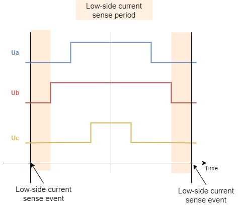
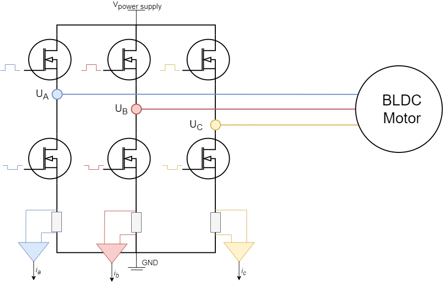
Low-side current sensing is probably the most common current sensing technique. The main reason why is because it does not require neither high-performance PWM rejection current sense amplifiers (as inline does) neither high-voltage supporting amplifiers (as high-side does). The shunt resistors are always placed in between low side mosfets and the ground making sure that the amplifiers always have very low voltages on their terminals. The main drawback of this approach is that, since the current passing through the shunt resistors is phase current only if the corresponding low side mosfet is ON, we can only measure it in those moments. The PWM frequency is usually 20 to 50 kHz, which means that the low-side mosfets turn on and off 20,000 to 50,000 times per second, therefore the synchronization in between PWM setting and ADC acquisition is very very important.
Low side current sensing for all the architectures is on our road-map and we are actively working on it. The main issue at the moment is very hardware specific synchronisation procedure of the PWM generation and ADC triggering. Therefore we are attacking one MCU architecture at the time. 😃
Using
LowsideCurrentSenseclass with inline current sensing hardwareIn the SimpleFOClibrary the low-side current sensing is implemented in the
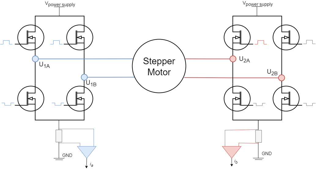
LowsideCurrentSenseclass. This class is designed to work with theBLDCDriverandStepperDriverclasses and it is used to measure the phase currents of the motor where the ADC conversions are synchoronised with the PWM generation of the driver. TheLowsideCurrentSenseclass is impletmets this synchonisation, and even though it is primarily designed to be used with the low-side current sensing hardware, it can also be used with the inline current sensing hardware. And in some cases it is even suggested to use it with the inline current sensing hardware such as for stm32 architecture, as it has much better performance since it is using DMA for ADC conversions.
Current sensing support per MCU architecture
Low side current sensing is currently supported for several MCU architectures supported by the SimpleFOClibrary. ESP32 architecture has the most generic support, supporting multiple motors per chip. Stm32 families f1, f4, l4, g4 and f7 are supported and support low-side sensing for only one motor. A special case of the STM32 board is the B-G431-ESC1 development kit which has very specific low-side implementation for its hardware configuration, and it is fully supported by the library. Samd21 architecture is under development, it has an initial support for only one motor, but for now as it has not been extensively tested, we suggest not to rely on our implementation. Teensy4 has an initial support for low-side sensing for one motor as well.
| MCU | Low-side Current sensing | ADC conversion type | Max PWM freqeuncy | supported ADC |
|---|---|---|---|---|
| Arduino (8-bit) | ❌ | - | - | - |
| Arduino DUE | ❌ | - | - | - |
| STM32 (in general) | ❌ | - | - | - |
| STM32f1 family | ✔️ | Interrupt | ~20kHz | all |
| STM32f4 family | ✔️ | Interrupt | ~25kHz | all |
| STM32g4 family | ✔️ | Interrupt | ~25kHz | all |
| STM32l4 family | ✔️ | Interrupt | ~25kHz | all |
| STM32f7 family | ✔️ | Interrupt | ~25kHz | all |
| STM32h7 family | ✔️ | Interrupt | ~25kHz | all |
| STM32 B_G431B_ESC1 | ✔️ | DMA | ~25kHz | all |
| ESP32 with MCPWM | ✔️ | Interrupts | ~20kHz | all |
| ESP32 with LEDC | ❌ | - | - | - |
| ESP8266 | ❌ | - | - | - |
| SAMD21 | ✔️ (one motor) | Interrupts | ~20kHz | one ADC |
| SAMD51 | ❌ | - | - | - |
| Teensy3 | ❌ | - | - | - |
| Teensy4 | ✔️ (inital) | Interrupts | ~20kHz | ADC1 |
| Raspberry Pi Pico | ❌ | - | - | |
| Portenta H7 | ❌ | - | - | - |
| Renesas (UNO R4) | ❌ (TBD) | - | - | - |
| Arduino Nano Matter(📢NEW) | ✔️(one motor) | DMA | N/A | ADC0 |
Important hardware considerations
Low-side current sensing requires very high synchronisation of the PWM generated by the driver and the ADC triggering. There are three main considerations to have in mind when choosing the MCU you wish to use and the driver you wish to use with the low-side current sensing:
- ADC conversion type - DMA or Interrupt based
- PWM frequency considerations
- Appropriate PWM and ADC pin considerations
See more info about driver paramers in the driver docs!
1. ADC conversion type
The low-side current sensing is supported for several architectures with essentially two different techniques: Interrupt based ADC conversion and DMA based ADC conversion. In the interrupt based ADC conversion, the ADC conversion is triggered by the PWM timer when at the center of the PWM duty cycle when all phases are grounded. In this case, the MCU has to wait for the ADC conversion to finish before it can do other tasks. In the DMA based ADC conversion, the ADC conversion is triggered by the PWM timer when at the center of the PWM duty cycle when all phases are grounded, but the ADC conversion is done in the background by the DMA controller. This allows the MCU to do other tasks while the ADC conversion is taking place.
RULE OF THUMB: ADC conversion type
As DMA based ADC conversion is much more efficient, it is recommended to use MCU architectures that support it if possible.
2. PWM frequency considerations
As the ADC conversion takes some time to finish and as this conversion has to happen only during the specific time window ( when all the phases are grounded - low-side mosfets are ON ) it is important to use an appropriate PWM frequency. PWM frequency will determine how long each period of the PWM is and in term how much time the low-side switches are ON. Higher PWM frequency will leave less time for the ADC to read the current values.
On the other hand, having higher PWM frequency will produce smoother operation, so there is definitely a trade-off here.
RULE OF THUMB: PWM frequency
The rule of thumb is to stay arround 20kHz.driver.pwm_frequency = 20000;
3. Appropriate PWM and ADC pin considerations
As ADC conversion has to be synchronised with the PWM generated on ALL the phases, it is important that all the PWM generated for all the phases have aligned PWM and that it supports triggering of the ADC conversion. Since the microcontrollers usually have more than one timer for PWM generation and more than one ADC for reading the analog values it is important to choose the right pins for the right phase.
RULE OF THUMB: PWM timer and ADC pins
In order to maximise your chances for the low-side current sensing to work well we suggest to make sure that the PWM pins chosen for your driver all belong to the same Timer, and the ADC pins chosen for your current sense all belong to the same ADC.
📢 Here is a quick guide to choosing appropriate PWM pins for different MCU architectures see in docs.
📢 Here is a quick guide to choosing appropriate ADC pins for different MCU architectures see in docs.
Hardware configuration
// LowsideCurrentSense constructor
//  - shunt_resistor  - shunt resistor value
//  - gain  - current-sense op-amp gain
//  - phA   - A phase adc pin
//  - phB   - B phase adc pin
//  - phC   - C phase adc pin (optional)
LowsideCurrentSense current_sense  = LowsideCurrentSense(0.01f, 20.0f, A0, A1, A2);
To instantiate the low-side current sensor using the SimpleFOClibrary just create an instance of the class LowsideCurrentSense. This class takes as a parameter shunt resistance value shunt_resistor, amplification gain gain and two or three ADC channel pins depending on the available measuring hardware that you might have. It is important to specify right adc channels for right driver/motor phase. So if your pin A0 measures the phase current A and pin A1 measures the phase current B make sure to put provide them to the constructor in that order.
Alternatively LowsideCurrentSense can be created by specifying the mV per Amp ratio mVpA, more common with hall sensor based current sense like ACS712.
// InlineCurrentSensor constructor
//  - mVpA  - mV per Amp ratio
//  - phA   - A phase adc pin
//  - phB   - B phase adc pin
//  - phC   - C phase adc pin (optional)
LowsideCurrentSense current_sense  = LowsideCurrentSense(66.0f,  A0, A1, A2);
Measuring 2 out of 3 currents
Field Oriented Control algorithm can run with both 2 or 3 phase current measurements. If measuring 2 out of 3 currents, when defining your LowsideCurrentSense class put the flag _NC (not connected) to the phase value you are not using.
For example if measuring the current on phases A (analog pin A0) and C (analog pin A1) and not measuring the current on the phase B, then you’ll define your current sense class as:
// LowsideCurrentSense constructor
LowsideCurrentSense current_sense  = LowsideCurrentSense(shunt_resistor, gain, A0, _NC, A1);
Some more examples:
// LowsideCurrentSense constructor
LowsideCurrentSense current_sense  = LowsideCurrentSense(shunt_resistor, gain, _NC, A0, A1); // when measuring B and C phase currents and not measuring A

// LowsideCurrentSense constructor
LowsideCurrentSense current_sense  = LowsideCurrentSense(shunt_resistor, gain, A0, A1, _NC); // when measuring A and B phase currents and not measuring C
// or
LowsideCurrentSense current_sense  = LowsideCurrentSense(shunt_resistor, gain, A0, A1); // when measuring A and B phase currents and not measuring C
Custom gains
The constructor of the LowsideCurrentSense class only allows you to specify one shunt resistor value and one amplification gain. If your hardware configuration has different shunt/amp values for different phases you can specify them by changing the gain_x attribute:
// default values of per phase gains
current_sense.gain_a = 1.0 / shunt_resistor / gain;
current_sense.gain_b = 1.0 / shunt_resistor / gain;
current_sense.gain_c = 1.0 / shunt_resistor / gain;
For example AliExpress DRV8302 board has all the current sensing phases inverted inverted. So in its case you can specify:
// inverse current sensing gain
current_sense.gain_a *= -1;
current_sense.gain_b *= -1;
current_sense.gain_c *= -1;
Synchronising the current sense with the driver PWM
Since the low-side current sensing technique requires triggering of the ADC acquisition exactly when all the low-side mosfets are ON (when all the phases are grounded), to use the LowsideCurrentSense with the FOC algorithm, first thing you’ll need to do is to associate (link) your current sense with the BLDCDriver:
// link current sense and driver
current_sense.linkDriver(&driver);
Current sense will be using driver parameters for different synchronisation and calibration procedures.
API change - SimpleFOClibrary v2.2.2
Driver linking to the current sense is introduced from the library version v2.2.2 in order to propagate different hardware specific parameters in between ADC and PWM timers needed for advanced synchronisation for current sensing.
Initialising the current sense
Once the current sense has been created and linked with the driver it can be initialised. This init() function configures the ADC hardware for reading and finds the zero offsets of the ADC for each channel.
// init current sense
current_sense.init();
Init function is responsible for
- configuring ADC for current sensing
- calibration - offset removal
If for some reason the ADC configuration fails this function will return 0 if everything went well the function will return 1. So we suggest you to check if the init function was executed successfully before continuing:
// init current sense
if (current_sense.init())  Serial.println("Current sense init success!");
else{
  Serial.println("Current sense init failed!");
  return;
}
When your current sense has been intialised and calibrated you can start measuring the currents!
Enable debugging output
If you wish to see a more verbose debugging output of the current sense configuration during the current_sense.init() and see more details about the configuration and possible errors, you can use the SimpleFOCDebug class. In order to enable the verbose debugging mode make sure to enable debugging before the current_sense.init() call, preferably at the top of the setup() function.
Serial.begin(115200); // to output the debug information to the serial
SimpleFOCDebug::enable(&Serial);
See more in the SimpleFOCDebug documentation.
📢 We strongly advise to use the debugging mode when starting with the SimpleFOClibrary. It provides much more information than the standard monitoring output and can help troubleshooting potentially problems, even MCU architecture specific ones.
Using the current sense with FOC algorithm
To use the LowsideCurrentSense with the FOC algorithm, first thing you’ll need to do is to associate (link) your current sense with the BLDCDriver:
BLCDriverXPWM driver = BLCDriverXPWM(...);
...
LowsideCurrentSense current_sense  = LowsideCurrentSense(...);

void setup(){
  ...
  // init driver
  driver.init();
  // link current sense and driver
  current_sense.linkDriver(&driver);
  ...
  current_sense.init();
  ...
}
Current sense will be using driver parameters for different synchronisation and calibration procedures.
API change - SimpleFOClibrary v2.2.2
Driver linking to the current sense is introduced from the library version v2.2.2 in order to propagate different hardware specific parameters in between ADC and PWM timers needed for advanced synchronisation for current sensing.
Once the driver is linked to the current sense, last step is to link the current sense with the motor you wish to use it with:
// link motor and current sense
motor.linkCurrentSense(¤t_sense);
Where to place the current_sense configuration in your FOC code?
It is very important that the the current sensing init function is called after the BLDCDriver init function is called. This will make sure that the driver is enabled when current sense calibration is taking place. Also, it is important that the current sense init function is called before initializing the motor and starting the foc algorithm with the initFOC function.
So the suggested code structure would be:
void setup(){
....
// driver init
driver.init();
// link the driver to the current sense
current_sense.linkDriver(&driver);
....
// motor init
motor.init();
....
// init current sense
current_sense.init();
// link the current sense to the motor
motor.linkCurrentSense(¤t_sense);
...
// start the FOC
motor.initFOC();
}
Function initFOC() will make sure that the BLDCDriver and LowsideCurrentSense classes are both well aligned, it is very important that the phase A of the current sense is exactly the phase A of the driver, phase B of the current sense exactly pahse B of the driver and the same for the phase C. To verify this, the initFOC will be calling the current sense’s function current_sense.driverAlign(...).
Alignment with the motor phases driverAlign(...)
The current sense and the driver alignment inside initFOC is done by calling the function:
current_sense.driverAlign(voltage_sensor_align);
This function will be using the driver instance (linked to the current sense with current_sense.linkDriver(&driver)) to apply the voltage (voltage can be set using the parameter motor.voltage_sensor_align) to each of the phases and checks if the measured currents correspond to the directions of the applied voltages. This alignment procedure is able to correct for:
- Incorrect order of adc pins
- Incorrect gain sign
If monitoring is enabled for the motor during the initFOC the monitor will display the alignment status:
0- fail1- success and nothing changed2- success but pins reconfigured3- success but gains inverted4- success but pins reconfigured and gains inverted
If you are sure in your configuration and if you wish to skip the alignment procedure you can specify set the skip_align flag before calling motor.initFOC():
// skip alignment procedure
current_sense.skip_align = true;
For example for the AliExpress DRV8302 board, you would have code similar to this:
// one possible combination of current sensing pins for SimpleFOCShield v2
// shunt - 5milliOhm
// gain - 12.22 V/V
LowsideCurrentSense current_sense = LowsideCurrentSense(0.005f, 12.22f, IOUTA, IOUTB, IOUTC);
void loop(){
....
// driver init
driver.init();
// link the driver to the current sense
current_sense.linkDriver(&driver);
....
// motor init
motor.init();
....
// init current sense
current_sense.init();
// link the current sense to the motor
motor.linkCurrentSense(¤t_sense);
...
// invert phase b gain
current_sense.gain_a *=-1;
current_sense.gain_b *=-1;
current_sense.gain_c *=-1;
// skip alignment
current_sense.skip_align = true;
...
// start the FOC
motor.initFOC();
}
See the full example for the Aliexpress DRB8302 based board in the library examples /examples/hardware_specific_examples/DRV8302_driver/esp32_current_control_low_side.
Standalone current sense
Since the low-side current sense has to be synchornised with PWM of a driver of interest it does not make sense to use it as a stand-alone sensor. But once you have linked the current sense with the driver you can use it to read your phase currents, overall current magnitude and DQ currents.
Reading the phase currents can be done by calling:
PhaseCurrent_s current = current_sense.getPhaseCurrents();
This function returns the PhaseCurrent_s structure that which has three variables a, b and c. So you can print them out for example;
Serial.println(current.a);
Serial.println(current.b);
Serial.println(current.c); // 0 if only two currents mode
If you are using only two phase current measurements in your InlineCurrentSense, it will return the third current current.c equal to 0.
Sometimes the phase currents are hard to interpret, therefore this current sense class enables you to read the transformed current vector magnitude. The absolute DC current the motor is drawing.
float current_mag = current_sense.getDCCurrent();
Futhermore if you have an access to the position sensor of the motor connected to the driver you can get signed value of the DC current the motor is drawing by providing it to the getDCCurrent method.
float current = current_sense.getDCCurrent(motor_electrical_angle);
Finally if you have the access to the motor position sensor you current sense class will be able to tell you the FOC currents D and Q that your motor is drawing.
DQCurrent_s current = current_sense.getFOCCurrents(motor_electrical_angle);
This function returns the DQCurrent_s structure which has two variables, d and q. You can print them out for example:
Serial.println(current.d);
Serial.println(current.q);
Example code
Here is a simple example of a low-side current sense using the SimpleFOClibrary and to read the motor currents directly.
#include <SimpleFOC.h>
// define the motor and the driver
BLDCMotor motor = BLDCMotor(...);
BLDCDriverXPWM driver = BLDCDriverXPWM(...);
// current sensor
// shunt resistor value
// gain value
// pins phase A,B
LowsideCurrentSense current_sense = LowsideCurrentSense(0.01, 50.0, A0, A1, A2);
void setup() {
// init driver
driver.init();
current_sense.linkDriver(&driver);
...
// init motor
motor.init();
...
// initialise the current sensing
current_sense.init();
motor.linkCurrentSense(¤t_sense);
...
motor.initFOC();
...
Serial.begin(115200);
Serial.println("Setup ready.");
}
void loop() {
// foc and motion controls
motor.loopFOC();
motor.move();
PhaseCurrent_s currents = current_sense.getPhaseCurrents();
Serial.print(currents.a*1000); // milli Amps
Serial.print("\t");
Serial.print(currents.b*1000); // milli Amps
Serial.print("\t");
Serial.println(currents.c*1000); // milli Amps
}