On this page
Current sense automatic alignment procedure
The current sense alignment to the motor phases is a crucial part of the motor control. In order that the FOC algorithm work properly, we need to make sure that the currents measured by the current sense correspond to the actual motor currents. This is a very important step because it is the first step in the motor control and it has to be done correctly in order for BLDC or Stepper motor to be able to move at all. 😃
This page gives a bit more details what is the reasoning behind the current sense alignment and how does the automatic alignment procedure work.
What does it mean to be aligned?
There are two main factors that define the alignment of the current sensing and the motor phases:
- Current sense ADC channel
Ameasures the current on the motor/driver phaseA, channelBmeasures the current on the motor/driver phaseB, etc. - The current sense ADC channels measure the phase current with the same polarity as the motor driver.
As this is a crucial part of the motor control, the SimpleFOClibrary provides an automatic current sense alignment procedure that will help you to align the current sense to the motor phases. Of course, if you are sure that the driver PWM pins, current sense ADC pins and gain values are correctly set, you can skip this step and set the current_sense.skip_align variable to true (see more in the current sense docs).
How does it work?
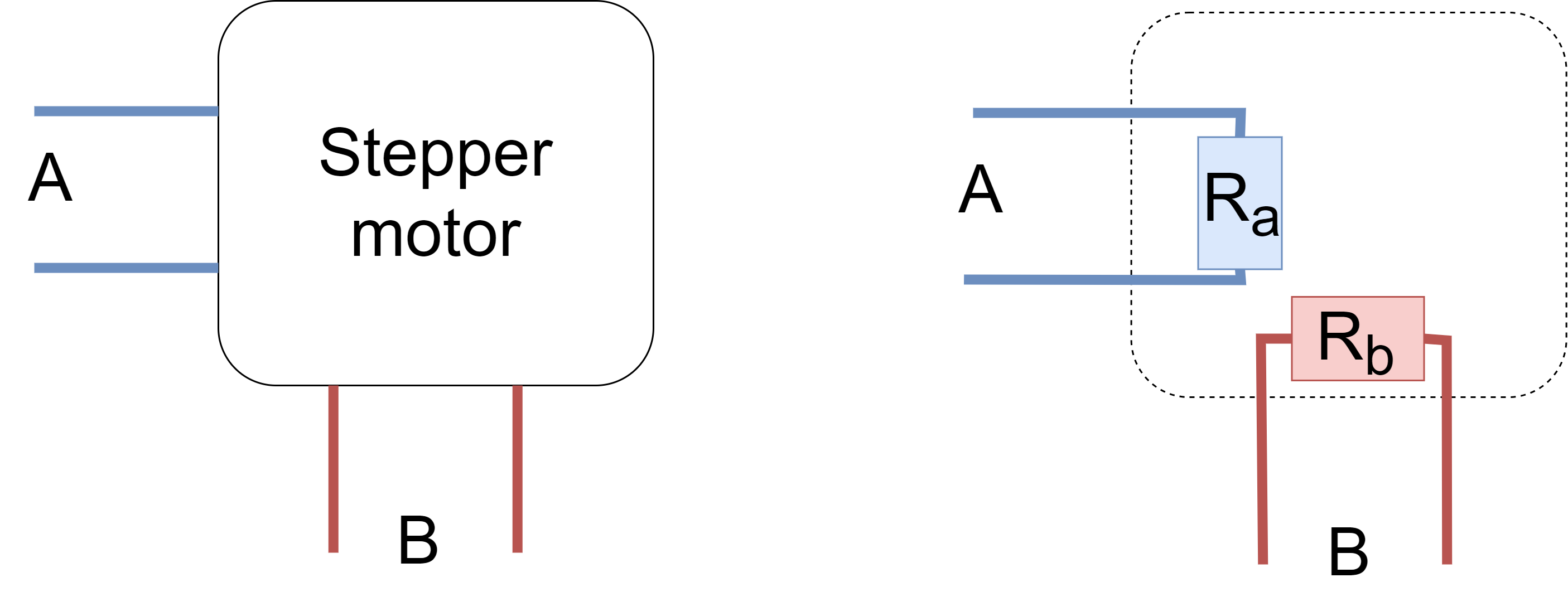
The procedure is simple and is based on the view of the motor as an electrical circuit with motor phases as resistors.
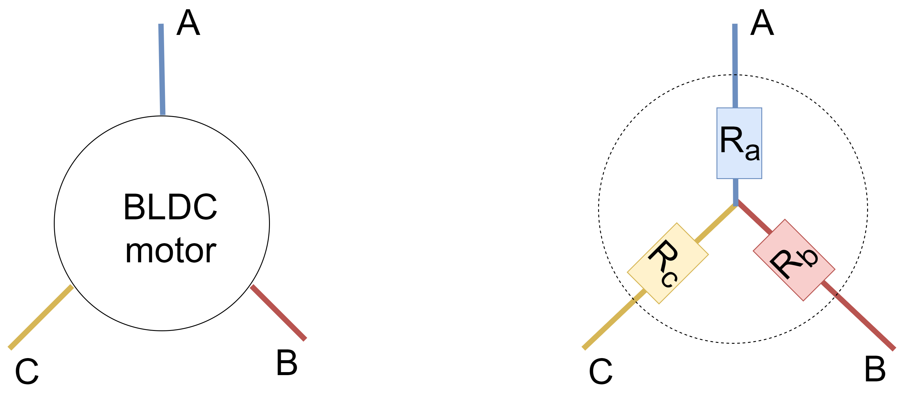
Also the assumption taken by the align is that the phase resistances of the motor are equal. This is a common assumption for the BLDC and Stepper motors and it is a good starting point for the current sense alignment.
The alignment procedure then applies phase volatges on one phase and keeps the other phases connected to the ground. Then by knowing the phase voltages applied and abstarcting the motor as a simple three resistance circuit, we can calculate the currents that should flow through the motor phases and compare them to the currents measured by the current sense. If the currents are not the same, the current sense is not aligned and the procedure will try to align it.
As the architecture of Stepper and BLDC motors is different the alignment procedure is also different.
- BLDC alignment procedure is described here: BLDC alignment procedure
- Stepper alignment procedure is described here: Stepper alignment procedure
BLDC alignment procedure
In the following sections I will try to explain the procedure in more detail. And I am sorry if this explanation is a bit of a mess. I will try to make it more clear in the future. 😃
The procedure steps in text
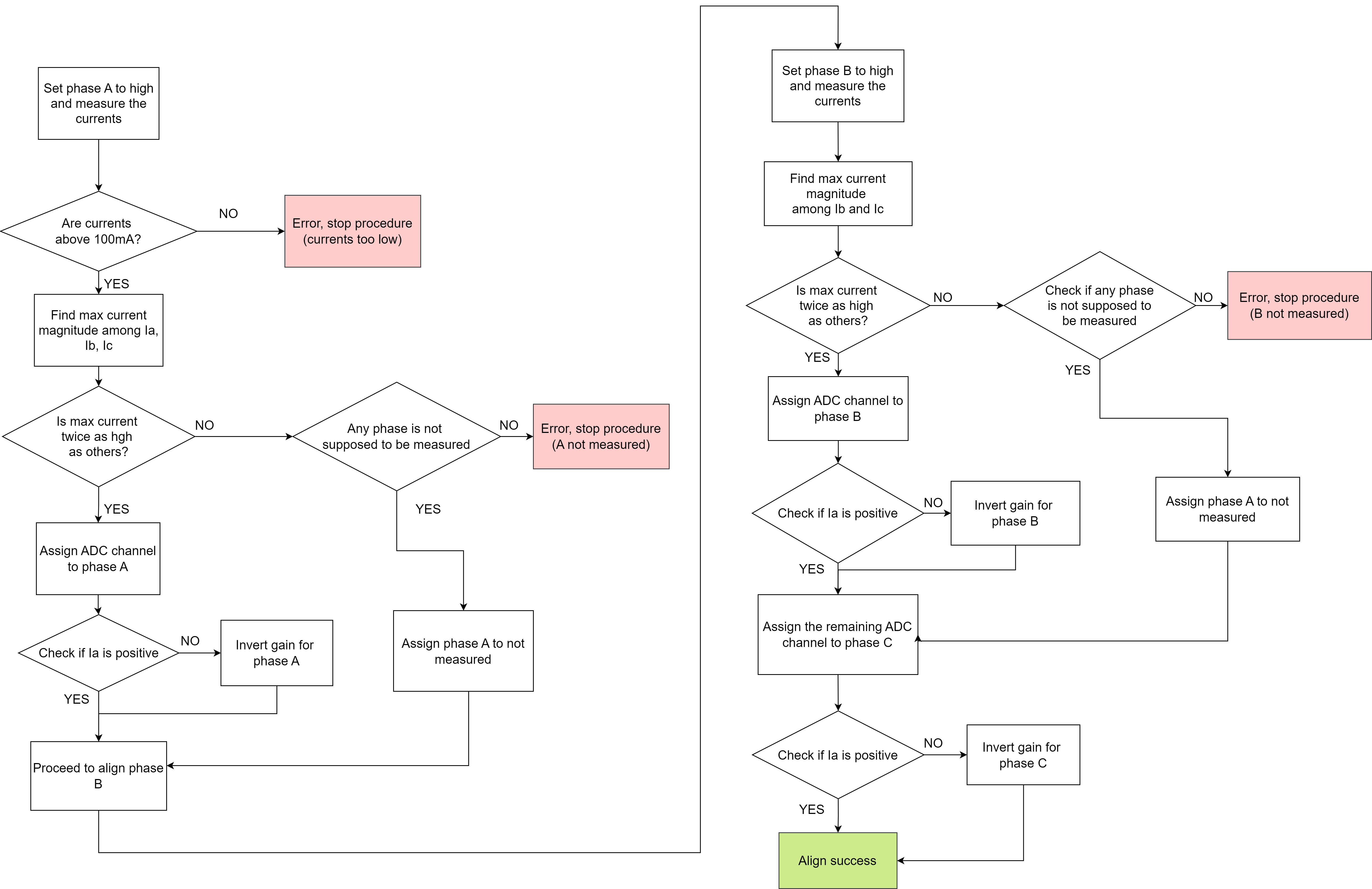
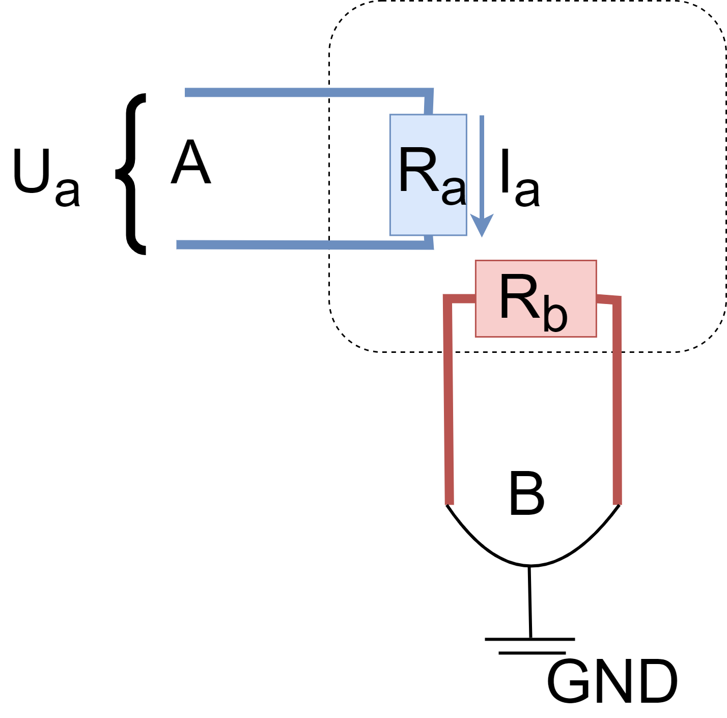
Set phase A to high and measure the currents
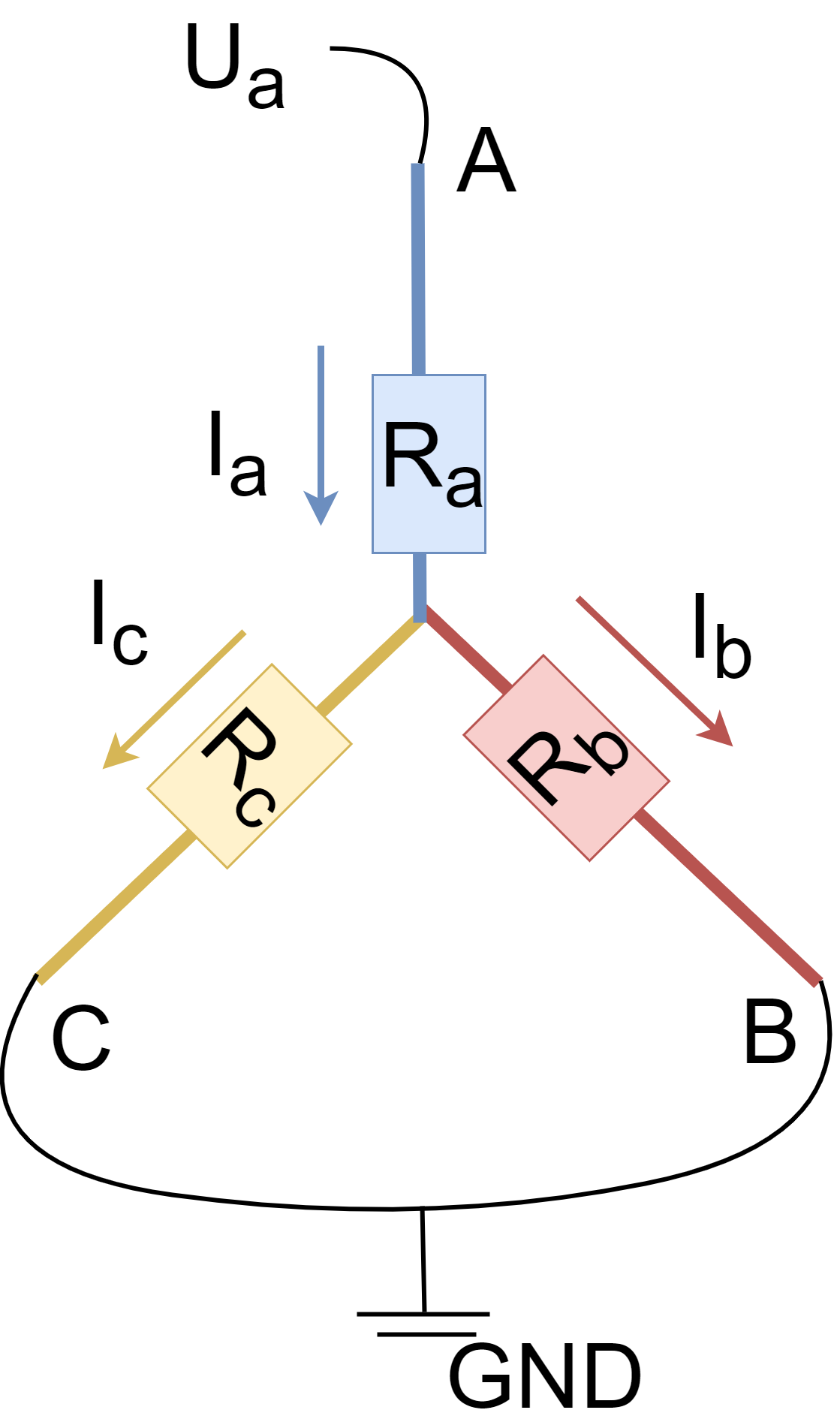
- We set a certain phase voltage \(U_a\) to the phase
Aand keep the phasesBandCgrounded (image on the right). - Then we measure the current on the phase
A,BandC(depending on their availability). - What we expect to see is that the current \(I_a\) on the phase
Ais the highest (twice as high as the current on the other phases) and positive. The current \(I_b\) and \(I_c\) on the phasesBandCshould be negative and have roughly half of the magnitude of the current \(I_a\) on the phaseA.
Initial current check
- First we check that the magnitudes of the measured currents are above 100mA.
- If they are not then we stop the procedure as the currents are too low to be measured accurately.
Find the current \(I_a\)
- Find the maximum current magnitude among \(I_a\),\(I_b\) and \(I_c\).
- Verify that its magnitude is roughly twice as high as the other two currents:
- If found, assign its ADC channel the phase
Aand verify that its polarity is positive (adapt invert the gain if necessary). - If there is no current twice as high as the other two currents, the phase
Ais not measured.
Verify that one of the motor phases is not supposed to be measured (does not have the assigned ADC pin/channel - ex. has_NC)- If there is a phase that is not supposed to be measured (current sense has 2 out 3 ADC pins specified), assign the phase
Aof the motor as not measured (ADC pin to_NC). - If all currents should be measured (all 3 ADC pins are specified in the current sense) there is an error and the procedure is stopped.
- If there is a phase that is not supposed to be measured (current sense has 2 out 3 ADC pins specified), assign the phase
- If we get to this step without errors the phase
Ais aligned with the ADC channelAof the current sense, and we can proceed to the alignment of theBandCphases.
- If found, assign its ADC channel the phase
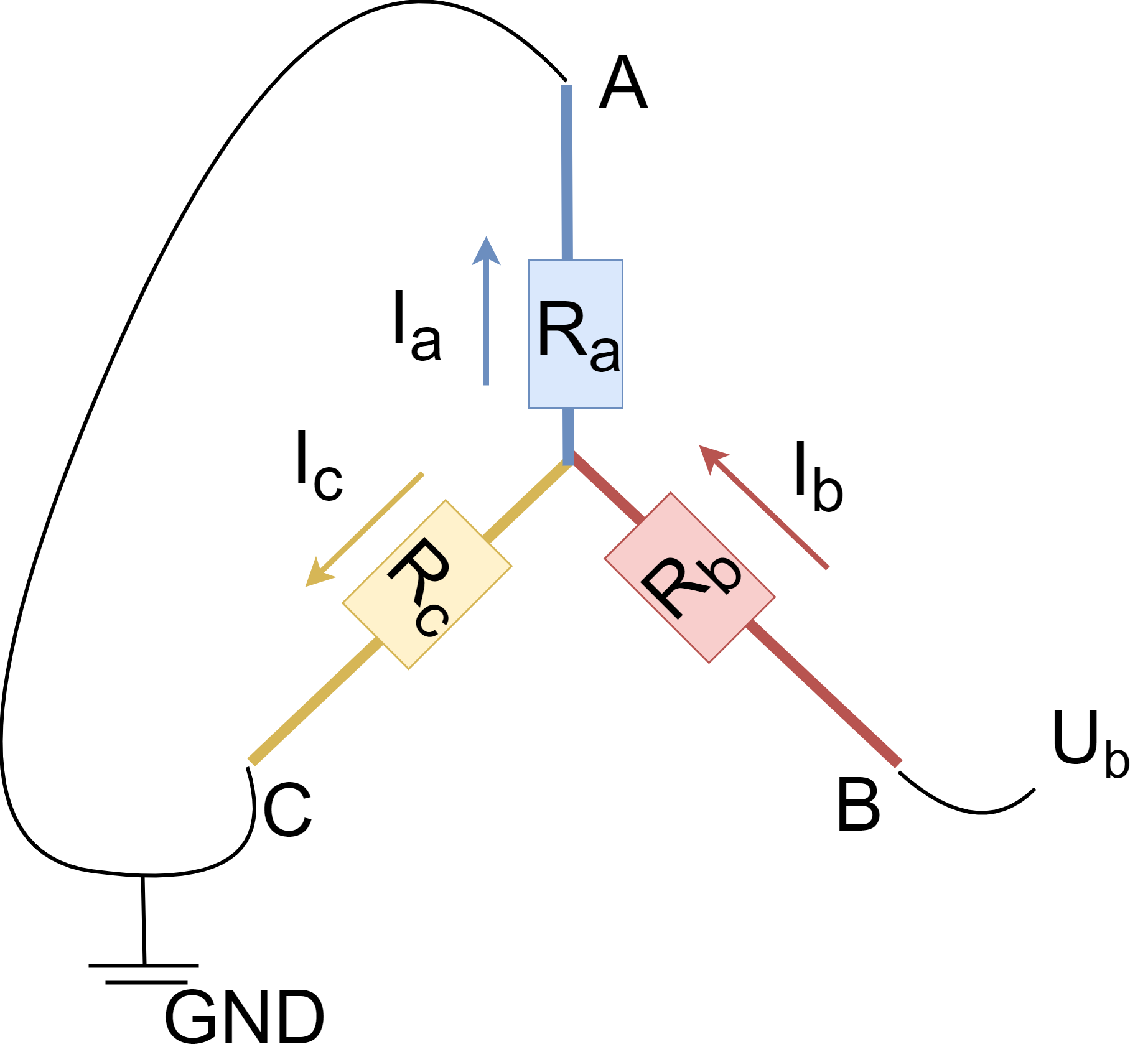
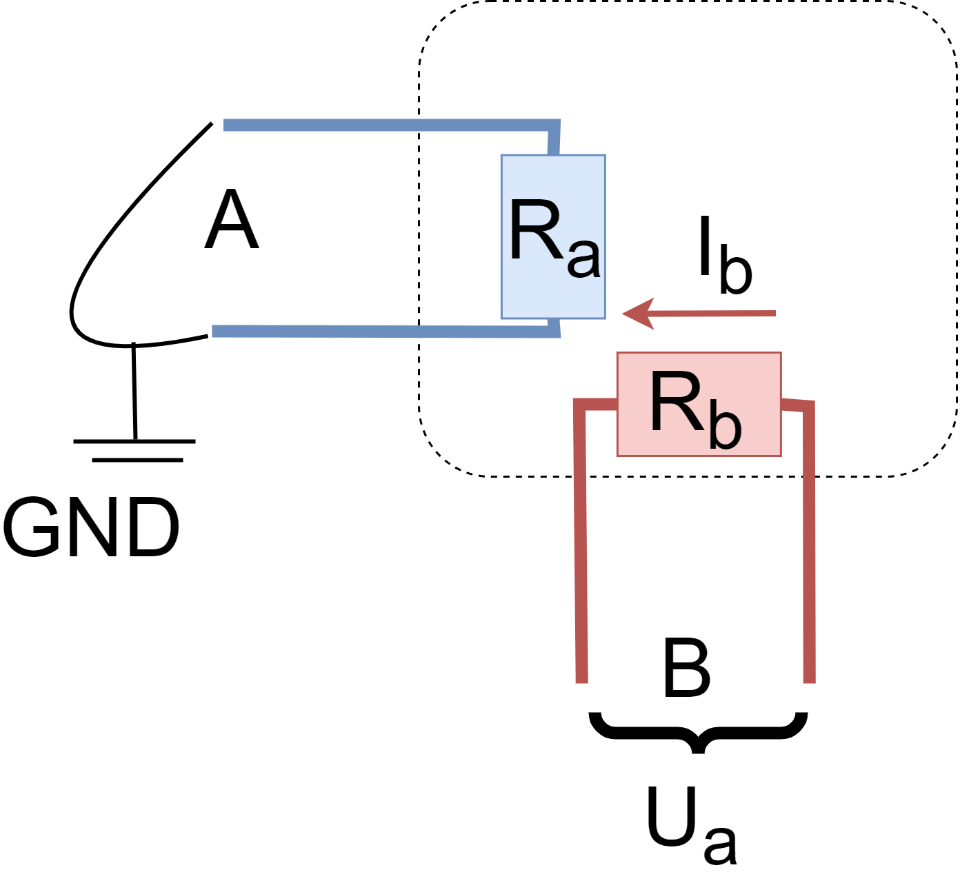
Set phase B to high and measure the currents
- We set a certain phase voltage \(U_b\) to the phase
Band keep the phasesAandCgrounded (image on the right). - Then we measure the current on the phase
A,BandC(depending on their availability). - What we expect to see is that the current \(I_b\) on the phase
Bis the highest (twice as high as the current on the other phases) and positive. The current \(I_a\) and \(I_c\) on the phasesAandCshould be negative and have roughly half of the magnitude of the current \(I_b\) on the phaseB.
Find the current \(I_b\)
- Find the maximum current magnitude among \(I_b\) and \(I_c\), and verify that it is roughly twice as high as the other two currents.
- If found, assign its ADC channel to the phase
Aand verify that its polarity is positive (adapt invert the gain if necessary). - If there is no current that is twice as high as the other two currents, the phase
Bis not measured.
Then we verify if there is one of the ADC channelsBorCthat are not supposed to be measured- If there is a phase that is not supposed to be measured (one of them is
_NC) we assign that the phaseBof the motor is not measured. - If both currents should have been measured (all 3 ADC pins are specified in the current sense) there is an error and the procedure is stopped.
- If there is a phase that is not supposed to be measured (one of them is
- If we get to this step without errors the phases
AandBare aligned with the ADC channelsAandBof the current sense
- If found, assign its ADC channel to the phase
Find the current \(I_c\)
- The third (only) remaining ADC channel can then be assigned to the phase
Cand verify that its polarity is negative (adapt invert the gain if necessary).
The procedure steps flow chart
The procedure in the code
The current sense alignment procedure is implemented in the current_sense.alignBLDCDriver() function which is called within motor.initFOC(). The function is called automatically when the motor is initialised and the current_sense.skip_align is not set to true. The code of the function can be found here.
Stepper alignment procedure
In the following sections I will try to explain the procedure in more detail. And I am sorry if this explanation is a bit of a mess. I will try to make it more clear in the future. 😃
The procedure steps in text
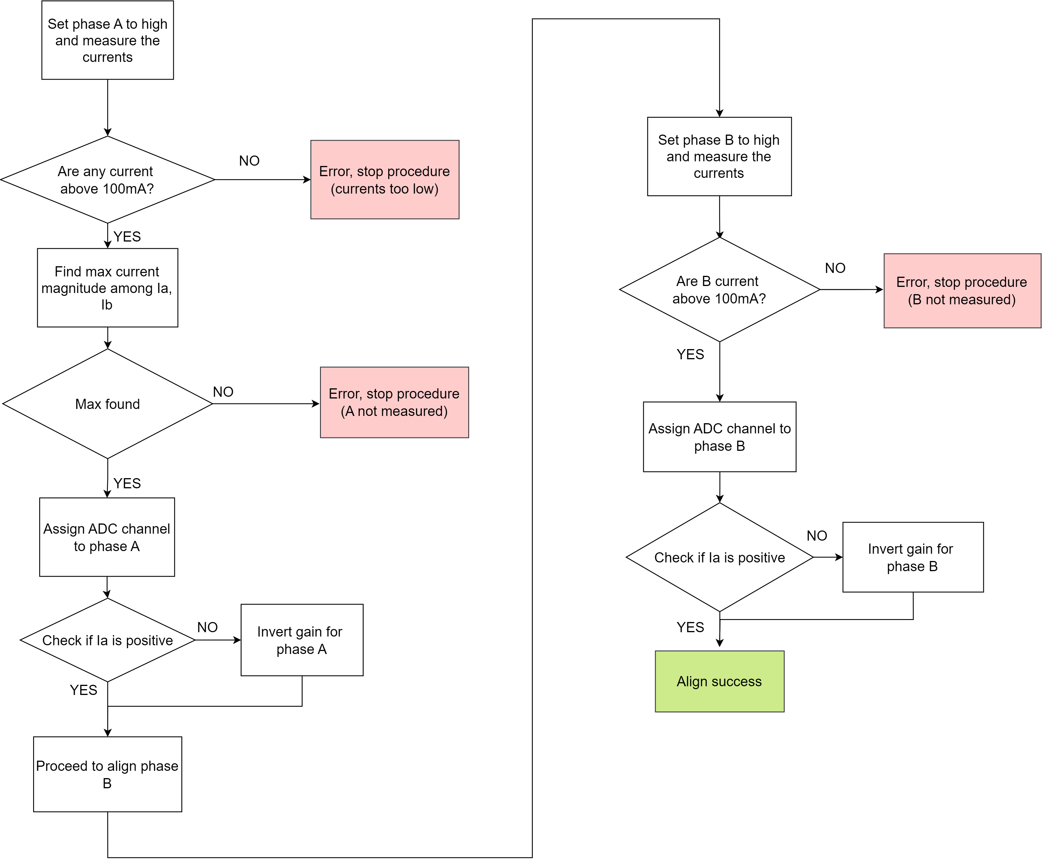
Set phase A to high and measure the currents
- We set a certain phase voltage \(U_a\) to the phase
Aand keep the phasesBgrounded (image on the right). - Then we measure the current on the phase
A,B. - What we expect to see is that the current \(I_a\) on the phase
Ais the highest and positive and the current \(I_b\) on the phasesBshould be negative alost zero.
Initial current check
- First we check that the magnitudes of the measured currents are above 100mA.
- If they are not then we stop the procedure as the currents are too low to be measured accurately.
Find the current \(I_a\)
- Find the maximum current magnitude among \(I_a\) and \(I_b\).
- Assign its ADC channel the phase
Aand verify that its polarity is positive (adapt invert the gain if necessary).
Set phase B to high and measure the currents
- We set a certain phase voltage \(U_b\) to the phase
Band keep the phasesAgrounded (image on the right). - Then we measure the current on the phase
A,B. - What we expect to see is that the current \(I_b\) on the phase
Bis the highest and positive and the current \(I_a\) on the phasesAshould be negative alost zero.
Find the current \(I_b\)
- Verify that the current \(I_b\) is the highest and assign its ADC channel the phase
Band verify that its polarity is positive (adapt invert the gain if necessary).
The procedure steps flow chart
The procedure in the code
The current sense alignment procedure is implemented in the current_sense.alignStepperDriver() function which is called within motor.initFOC(). The function is called automatically when the motor is initialised and the current_sense.skip_align is not set to true. The code of the function can be found here.