On this page
Velocity control example
using Drotek’s L6234 driver
Drotek’s L6234 breakout board is a very minimalistic 3-phase BLDC motor driver and is very suitable for jump-starting your FOC experience. Here we the velocity control example project using the SimpleFOClibrary and this hardware:
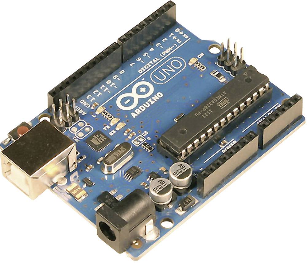
Connecting everything together
For a bit more in depth explanation of Arduino UNO and L6234 connection please check the connection examples.
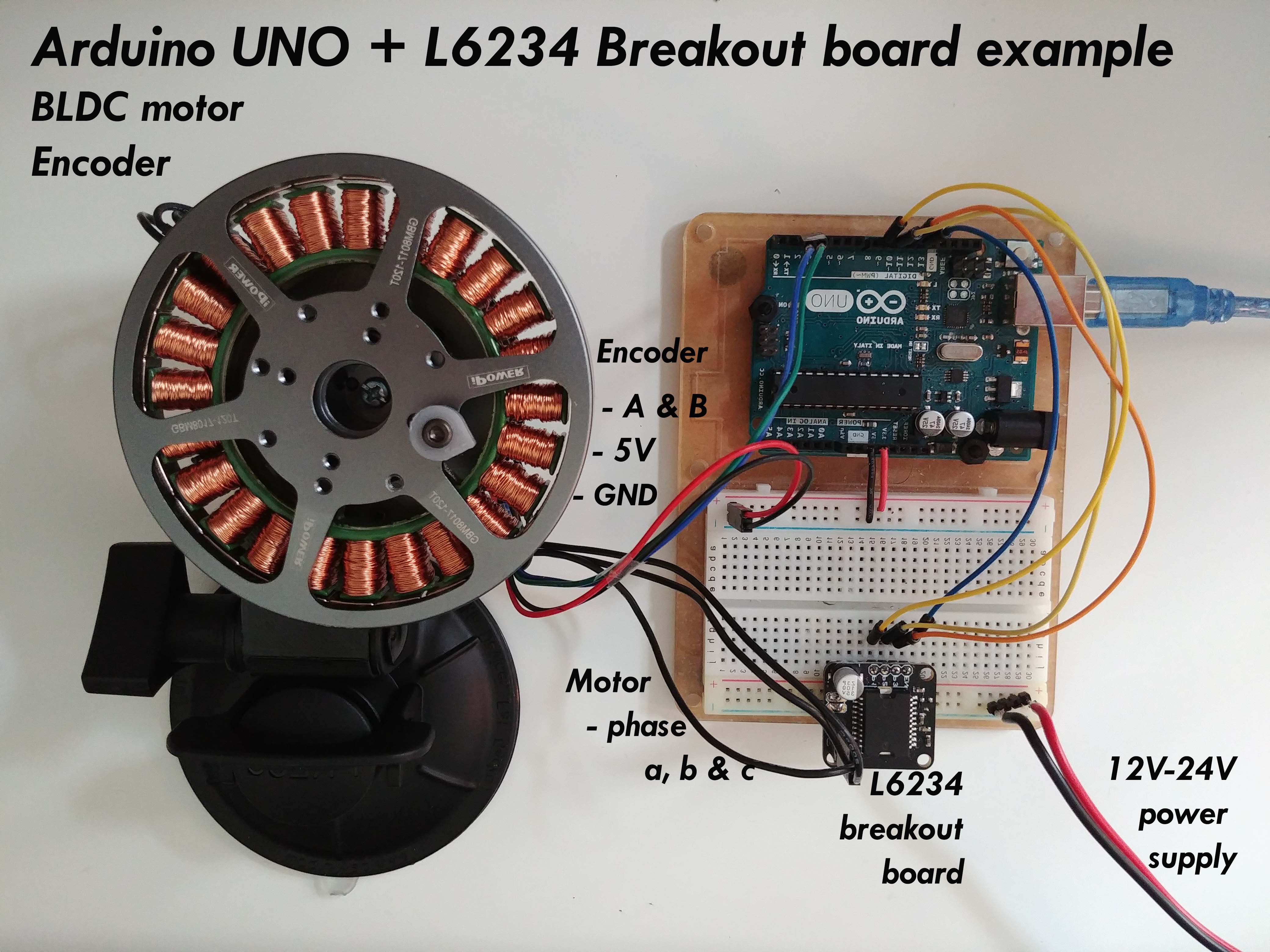
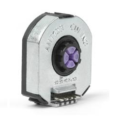
Encoder
- Encoder channels
AandBare connected to the Arduino’s external interrupt pins2and3.
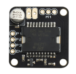
L6234 breakout board
- Connected to the arduino pins
9,10and11(you can use also pins5and6). - Additionally you can connect the
enablepin to the any digital pin of the arduino the picture shows pin8but this is optional. You can connect the driver enable directly to 5v. - Make sure you connect the common ground of the power supply and your Arduino
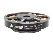
Motor
- Motor phases
a,bandcare connected directly to the driver outputs
Arduino code
Let’s go through the full code for this example and write it together. First thing you need to do is include the SimpleFOC library:
#include <SimpleFOC.h>
Make sure you have the library installed. If you still don’t have it please check the get started page
Encoder code
First we define the Encoder class with the A and B channel pins and number of impulses per revolution.
// define Encoder
Encoder encoder = Encoder(2, 3, 2048);
Then we define the buffering callback functions.
// channel A and B callbacks
void doA(){encoder.handleA();}
void doB(){encoder.handleB();}
In the setup() function we initialize the encoder and enable interrupts:
// initialize encoder hardware
encoder.init();
// hardware interrupt enable
encoder.enableInterrupts(doA, doB);
And that is it, let’s setup the motor.
For more configuration parameters of the encoders please check the Encoder class docs. Motor code
First we need to define the BLDCMotor class with the number of pole pairs (14)
// define BLDC motor
BLDCMotor motor = BLDCMotor(14);
If you are not sure what your pole pairs number is please check the find_pole_pairs.ino example. Next we need to define the BLDCDriver3PWM class with the PWM pin numbers of the motor and the driver enable pin
// define BLDC driver
BLDCDriver3PWM driver = BLDCDriver3PWM(9, 10, 11, 8);
Then in the setup() we configure first the voltage of the power supply if it is not 12 Volts and init the driver.
// power supply voltage
// default 12V
driver.voltage_power_supply = 12;
driver.init();
Then we tell the motor which control loop to run by specifying the motor.controller variable.
// set control loop type to be used
// MotionControlType::torque
// MotionControlType::velocity
// MotionControlType::angle
motor.controller = MotionControlType::velocity;
Now we configure the PI controller parameters
// velocity PI controller parameters
// default P=0.5 I = 10
motor.PID_velocity.P = 0.2;
motor.PID_velocity.I = 20;
//default voltage_power_supply
motor.voltage_limit = 6;
Additionally we can configure the Low pass filter time constant Tf
// velocity low pass filtering
// default 5ms - try different values to see what is the best.
// the lower the less filtered
motor.LPF_velocity.Tf = 0.01;
For more information about the velocity control loop parameters please check the doc.
And finally we connect the encoder and the driver to the motor, do the hardware init and init of the Field Oriented Control.
// link the motor to the sensor
motor.linkSensor(&encoder);
// link driver
motor.linkDriver(&driver);

// initialize motor
motor.init();
// align encoder and start FOC
motor.initFOC();
The last peace of code important for the motor is of course the FOC routine in the loop function.
void loop() {
// iterative FOC function
motor.loopFOC();

// iterative function setting and calculating the velocity loop
// this function can be run at much lower frequency than loopFOC function
motor.move(target_velocity);
}
That is it, let’s see the full code now!
For more configuration parameters and control loops please check the BLDCMotor class doc. Full Arduino code
To the full code I have added a small serial commander interface, to be able to change velocity target value in real time.
#include <SimpleFOC.h>

// define BLDC motor
BLDCMotor motor = BLDCMotor( 14 );
BLDCDriver3PWM driver = BLDCDriver3PWM(9, 10, 11, 8);

// define Encoder
Encoder encoder = Encoder(2, 3, 2048);
// channel A and B callbacks
void doA(){encoder.handleA();}
void doB(){encoder.handleB();}

// velocity set point variable
float target_velocity = 0;
// commander interface
Commander command = Commander(Serial);
void onTarget(char* cmd){ command.scalar(&target_velocity, cmd); }

void setup() {

  // initialize encoder hardware
  encoder.init();
  // hardware interrupt enable
  encoder.enableInterrupts(doA, doB);

  // power supply voltage
  // default 12V
  driver.voltage_power_supply = 12;
  driver.init();
  // link the motor to the driver
  motor.linkDriver(&driver);

  // set control loop type to be used
  motor.controller = MotionControlType::velocity;

  // velocity PI controller parameters
  // default P=0.5 I = 10
  motor.PID_velocity.P = 0.2;
  motor.PID_velocity.I = 20;
  //default voltage_power_supply
  motor.voltage_limit = 6;

  // velocity low pass filtering
  // default 5ms - try different values to see what is the best.
  // the lower the less filtered
  motor.LPF_velocity.Tf = 0.01;


  // link the motor to the sensor
  motor.linkSensor(&encoder);

  // initialize motor
  motor.init();
  // align encoder and start FOC
  motor.initFOC();

  // add target command T
  command.add('T', doTarget, "target velocity");

  // monitoring port
  Serial.begin(115200);
  Serial.println("Motor ready.");
  Serial.println("Set the target velocity using serial terminal:");
  _delay(1000);
}


void loop() {
  // iterative foc function
  motor.loopFOC();

  // iterative function setting and calculating the velocity loop
  // this function can be run at much lower frequency than loopFOC function
  motor.move(target_velocity);

  // user communication
  command.run();
}