On this page
- BLDC Motor configuration
- Step 1. Creating the instance of the BLDC motor
- Step 2. Linking the sensor
- Step 3. Linking the driver
- Step 4. Linking the current sense
- Step 5. Configuration paramters
- Step 6. Align motor and all the sensors - Field Oriented Control init
- Step 7. Real-time motion control
- User interaction
- Digging deeper
- Example code
BLDC Motor configuration
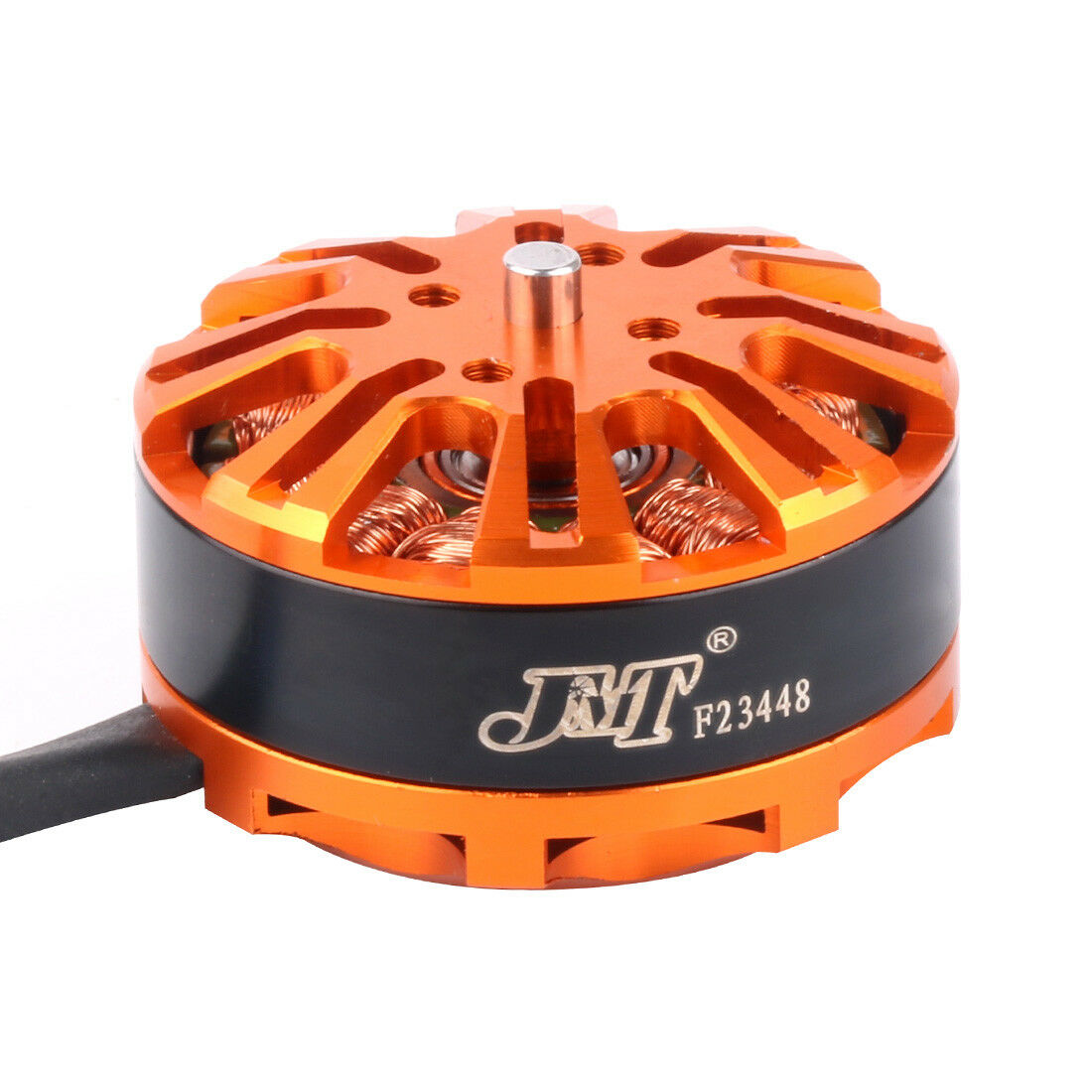
All BLDC motors are handled with the BLDCMotor class. This class implements:
- BLDC FOC algorithm
- Motion control loops
- Monitoring
Step 1. Creating the instance of the BLDC motor
To instantiate the BLDC motor we need to create an instance of the BLDCMotor class and provide it the number of pole pairs of the motor.
//  BLDCMotor(int pp, (optional R, KV, Lq, Ld))
//  - pp  - pole pair number
//  - R   - phase resistance value [Ohm] - optional
//  - KV  - motor KV rating [rpm/V] - optional
//  - Lq  - q axis inductance value [H] - optional
//  - Ld  - d axis inductance value [H] - optional
BLDCMotor motor = BLDCMotor(11, 10.5, 120, 0.001, 0.001);
pole_pairsis the number of pole pairs of your motor (Required)Ris the phase resistance of your motor (optional, used for current control modes),KVis the motor KV rating (optional, used for current control modes),Lqis the q axis inductance value (optional, used for current control modes),Ldis the d axis inductance value (optional, used for current control modes).
Pole pair number
If you are not sure what yourpole_pairsnumber is. The library provides an example code to estimate yourpole_pairsnumber in the examplesexamples/utils/calibration/find_pole_pairs_number.ino.
Motor phase resistance, inductance and KV rating
Motor parameters in SimpleFOClibrary are optional but they are used for:
- Estimated current torque mode - to estimate the motor current based on the voltage command and motor parameters
- FOC current control
- Advanced FOC control features - to compensate for cross-coupling
- Auto-tunning current PI controllers - to set the PI controller gains based on the motor parameters
If you need some of these features and you do not have the motor parameters there are a couple of options:
- Try to find them in the datasheet and verify them using this guide.
- Manually measure phase resitance and KV rating using the guides in the practical section
- Automatically measure them using the
characteriseMotor()function - guide here.
Go here fore more practical guides
Step 2. Linking the sensor
Once when you have the motor defined and the sensor initialized you need to link the motor and the sensor by executing:
// link the sensor to the motor
motor.linkSensor(&sensor);
Method linkSensor is able to link the motor to any sensor implemented in this library. The sensor will be used to determine electrical position of the motor for the FOC algorithm as well as for the motion control loops of velocity and position.
See position sensor documentation
Pro Tip
If sensor velocity too noisy, increase the time between veclocity calculations by setting the
sensor.min_elapsed_timevariable. For example:sensor.min_elapsed_time = 0.001; // seconds - default 0.0001s - 100usThis will improve the velocity estimation but it will add some lag to the velocity response.
Step 3. Linking the driver
Once when you have the motor defined and the driver initialized you need to link the motor and the driver by executing:
// link the driver to the motor
motor.linkDriver(&driver);
The BLDCMotor class expect to receive a BLDCDriver class instance, implemented by default with classes BLDCDriver3PWM and BLDCDriver6PWM. The driver deals with all the hardware specific operations related to specific microcontroller architecture and driver hardware.
Step 4. Linking the current sense
If you have a current sensor current_sense you can link it to the motor using:
// link the current sensor to the motor
motor.linkCurrentSense(¤t_sense);
This linking step is only necessary if you have a current sense supported by this library.
See current sense documentation
Step 5. Configuration paramters
If you choose not to set some of the configuration parameters they will take values defined in the defaults.h file. Check the library source code to dig deeper.
Step 5.1 PWM Modulation type
There are four types of Field Oriented Control modulation types implemented for BLDC motors:
- Sinusoidal PWM modulation
- Space Vector PWM modulation
- Block commutation - beneficial for current control applications
- Trapesoidal 120
- Trapesoidal 150
You can set them by changing the motor.foc_modulation variable:
// choose FOC modulation
// FOCModulationType::SinePWM; (default)
// FOCModulationType::SpaceVectorPWM;
// FOCModulationType::Trapezoid_120;
// FOCModulationType::Trapezoid_150;
motor.foc_modulation = FOCModulationType::SpaceVectorPWM;
Sinusoidal PWM and Space vector commutation patters will produce sinusoidal currents and smooth operation but block commutation will be faster to execute, therefore more suitable for higher velocities. It is suggested to use the Trapesoidal 120 commutation with Hall sensors. Other commutation patterns will work as well but this one will have the best performance.
FOC currents torque control requirements
FOC torque control requires sinusoidal currents therefore please use either Sinusoidal PWM or Space vector PWM
For more information about the theory of these approaches please and source code implementation check the FOC implementation docs or visit the digging deeper section.
Step 5.2 Sensor and motor aligning parameters
The voltage used for the motor and sensor alignment set the variable motor.voltage_sensor_align:
// aligning voltage [V]
motor.voltage_sensor_align = 3; // default 3V
If your sensor is an encoder and it has an index pin, you can set the index search velocity value by setting the variable motor.velocity_index_search:
// incremental encoder index search velocity [rad/s]
motor.velocity_index_search = 3; // default 1 rad/s
Step 5.3 Position sensor offset
For some applications it is convenient to specify the sensor absolute zero offset, you can define it by changing the parameter motor.sensor_offset:
// sensor offset [rad]
motor.sensor_offset = 0; // default 0 rad
This parameter can be changed in real-time.
Step 5.4 Motor parameters - phase resistance, inductance and KV rating
Motor phase resistance, inductance and KV rating are optional parameters which are used for current based torque modes. These variables can used to estimate the motor current in the estimated torque mode and to tune PI control loops. If user specifies the motor.phase_resistance, motor.axis_inductance (or before v2.4.0 motor.phase_inductance) motor.KV_rating (either in constructor or in the setup() function) the library will use these valus. In the setup function you can change this parameter by setting:
// motor phase resistance [Ohms]
motor.phase_resistance = 2.54; // Ohms - default not set
// motor KV rating [rpm/V]
motor.KV_rating = 100; // rpm/volt - default not set
// motor axis inductance [H]
motor.axis_inductance.d = 0.001; // H - default not set
motor.axis_inductance.q = 0.001; // H - default not set
These parameters can also be measured using the motor.characteriseMotor() above How can I measure the phase resistance and inductance? section.
Step 5.5 Torque control mode
There are 4 different torque control modes implemented in the Arduino SimpleFOClibrary:
DC current and FOC current require current sensing and are controlling current and limiting the real current the motor is drawing, whereas estimated current mode approximates the motor current using the motor parameters and does not use any current sensing. Finally, voltage mode is the most basic torque control mode which directly sets the voltage to the motor without any current control. Read more in torque control docs.
The torque mode can be set by changing the motor attribute torque_controller.
// set torque mode to be used
// TorqueControlType::voltage    ( default )
// TorqueControlType::estimated_current
// TorqueControlType::dc_current
// TorqueControlType::foc_current
motor.torque_controller = TorqueControlType::foc_current;
Each torque control loop has their own set of parameters and can be combined with any motion control loop.
See more info about torque control modes
Step 5.6 Motion control parameters
There are 3 different closed loop control strategies implemented in the Arduino SimpleFOClibrary:
- Torque control loop
- Velocity motion control
- Position/angle motion control
Additionally SimpleFOClibrary implements two open loop control strategies as well:
The user can also add thier own custom motion control strategy by implementing the motion control callback function. Read more about it in the motion control docs. This mode can be selected using the MotionControlType::custom value of the motor.controller variable and by linking the motion control callback function motor.linkCustomMotionControl(&my_motion_control_function).
You set it by changing the motor.controller variable.
// set motion control loop to be used
// MotionControlType::torque            - torque control
// MotionControlType::velocity          - velocity motion control
// MotionControlType::angle             - position/angle motion control
// MotionControlType::angle_nocascade   - position/angle motion control without cascade structure
// MotionControlType::velocity_openloop    - velocity open-loop control
// MotionControlType::angle_openloop       - position open-loop control
// MotionControlType::custom            - custom motion control
motor.controller = MotionControlType::angle;
Important!
This parameter doesn't have a default value and it has to be set before real-time execution starts.
Each motion control strategy has its own parameters and can be combined with any torque control mode. For more information about the motion control modes and their parameters check the motion control docs.
// set control loop type to be used
motor.controller = MotionControlType::angle;

// controller configuration based on the control type
motor.PID_velocity.P = 0.2;
motor.PID_velocity.I = 20;
motor.PID_velocity.D = 0.001;

// velocity low pass filtering time constant
motor.LPF_velocity.Tf = 0.01;

// angle loop controller
motor.P_angle.P = 20;

// motion control limits
// angle loop velocity limit
motor.updateVelocityLimit(50);
// either voltage limit
motor.updateVoltageLimit(12); // Volts -  default driver.voltage_limit
// or current limit - if phase_resistance set
motor.updateCurrentLimit(1); // Amps -  default 2 Amps
See more info about motion control parameters
Step 5.7 Configuration done - motor.init()
Finally the configuration is terminated by running init() function which prepares all the hardware and software motor components using the configured values.
// initialize motor
motor.init();
Step 6. Align motor and all the sensors - Field Oriented Control init
After the position sensor, current sense, driver and the motor are configured, and before we can start the motion control we need to align all hardware components in order to initialize the FOC algorithm. This is done in the scope of the function motor.initFOC()
// align sensor and start FOC
motor.initFOC();
This function does several things:
- Checks if driver (and current sense if available) are well initialised
- Checks/modifies position sensor direction in respect to the motor’s direction
- Searches for encoder index if necessary
- Finds the motor electrical offset in respect to the position sensor
- Checks/modifies current sense pinout and gains signs if one available to make sure it aligned with the driver
See more info about the theory of alignment See more info about implementation of initFOC()
If for some reason the initFOC fails this function will return 0 and it will disable your motor and display you a message what is wrong (when using the monitoring ). If everything is well configured, the call of this function will return 1 and the our setup is done, FOC is ready to be used! So we suggest you to check if the init function was executed successfully before continuing:
// init FOC
if (motor.initFOC())  Serial.println("FOC init success!");
else{
  Serial.println("FOC init failed!");
  return;
}
The alignment procedure will have to move your motor several times and might not be desirable behavior, therefore for most of the position sensors (except encodes) and current senses, this alignment procedure can be skipped by following the steps 6.1 an 6.2.
Step 6.1 Skip alignment - position sensor
If you are using absolute sensors such as magnetic sensors or hall sensors, once you have done the alignment procedure and once you have the motor’s zero electrical offset sensor direction you no longer need the full calibration sequence.
In this case you can set the sensor offset zero_electric_offset and sensor direction sensor_direction in the motor parameters to avoid the alignment procedure:
// set calibration values
motor.zero_electric_offset  = 2.15; // rad
motor.sensor_direction = Direction::CW; // CW or CCW
// then call initFOC()
motor.initFOC();
You can find these values by running the find_sensor_offset_and_direction.ino example.
If you set either of these two values the initFOC will skip that part of the calibration. For example, for encoder sensors the zero electrical offset changes all the time but the sensor direction will stay the same so you can provide it and skip a large part of the calibration sequence.
Tip
For encoders, the
zero_electric_offsetcannot be known in advance, but thesensor_directioncan be set to skip that part of the calibration sequence. This removes the need for large movement amplitude in the alignment procedure.
Step 6.2 Skip alignment - current sense
For the current sensors it is as well possible to avoid the calibration procedure an that is done by specifying the curren sense flag called skip_align:
current_sense.skip_align = true; // default false
But make sure that all of your gains are well set and all of your ADC pins are aligned to the driver/motor phases.
Step 7. Real-time motion control
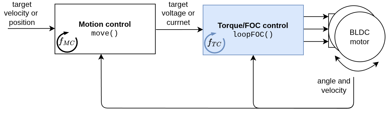
The real-time motion control of the SimpleFOClibrary is realized with two functions:
motor.loopFOC()- low level torque controlmotor.move(float target)- high level motion control
The loopFOC() function implements the low level torque control loop of the FOC algorithm. It is responsible for getting the motor angle from the sensor, calculating the current or voltage commands based on the torque control mode and setting the appropriate voltages to the motor phases using the driver.
// Function running the low level torque control loop
// it calculates the gets motor angle and sets the appropriate voltages
// to the phase pwm signals
// - the faster you can run it the better Arduino UNO ~1ms, Bluepill ~ 100us
motor.loopFOC();
See more info about Torque/FOC control
This function is execution time is critical for real-time control. Therefore it is very important that the motor.loopFOC() function is executed as fast as possible.
Tip
You can check the time between calls of the
loopFOC()function by reading themotor.loopfoc_time_usvariable which provides averaged time between calls of theloopFOC()function in microseconds. The faster you can run this function the better, for example on Arduino UNO you can expect to run it at around 1ms and on Bluepill at around 100us. Aim to run this loop at least at 1kHz for good performance, but the faster the better.
The motor.move() function implements the high level motion control loop. It is responsible for calculating the target voltage or current based on the motion control mode and the target value provided by the user.
// Function executing the motion control loops configured by the motor.controller parameter of the motor.
// - This function doesn't need to be run upon each loop execution - depends of the use case
//
// target  Either torque, angle or velocity based on the motor.controller
//         If it is not set the motor will use the target set in its variable motor.target
motor.move(target);
See more info about motion control
The target parameter is optional and if it is not set, the target value will be set by the public motor variable motor.target. The equivalent code would be:
motor.target = 2;
motor.move();
Tip
As well as for
loopFOC()function, the time betweenmove()call can be read in real-time. Themotor.move_time_usvariable provides averaged time between calls of themove()function in microseconds. Depending on the motion control mode and the use case, this function doesn’t need to be run upon each loop execution, therefore you can set themotor.motion_downsampleparameter to run it less often and save some processing time for theloopFOC()function.
Step 7.1 Place the loopFOC() and move() functions in the loop()
Finally, to run the real-time control, you need to place the motor.loopFOC() and motor.move() functions in the Arduino loop(). The loopFOC() function should be called as fast as possible, while the move() function can be called less often depending on the use case.
void loop() {
    motor.loopFOC();
    motor.move();
}
You want these functions to be called as much as possible and as regularly as possible. It is important not to use any delay() functions in the loop() or any other functions that take a long time to execute!
If you need to run other more time-consuming functions in the loop(), you can consider running the loopFOC() function in a hard real-time loop using Timers or RTOS. This way you can ensure that the loopFOC() function is called at a regular interval regardless of what else is happening in the loop().
See how to run hard-real-time control loops using Timers
Step 7.2 Motion control downsampling
In some motion control applications, especially for higher-end microcontrollers, where to loop can run at 20kHz, it will make sense run multiple torque control loops for each motion control loop. This can have a great impact on the smoothness and can provide better high-speed performance. Therefore this library enables a very simple downsampling strategy for the move() function which is set using the parameter motor.motion_downsample:
// downsampling value
motor.motion_downsample = 5; // - times (default 0 - disabled)
The downsampling strategy works in a very simple way, even though the motor.move() is called in each arduino loop it will only be executed each motor.motion_downsample calls. This parameter si optional and can be configured in real-time.
BEWARE: Motion control impact
Different values of the downsampling might require a bit of tuning of motion parameters.
See more info about motion control downsampling
User interaction
SimpleFOClibrary implements two types of real-time user interaction:
Digging deeper
For more theoretical explanations and source code implementations of the FOC algorithm and the motion control approaches check out the digging deeper section.
Example code
A simple BLDC motor torque control using voltage based on the FOC algorithm.
/**
 * Torque control example using voltage control loop.
 */
#include <SimpleFOC.h>

// BLDC motor instance
BLDCMotor motor = BLDCMotor(11);
// driver instance
BLDCDriver3PWM driver = BLDCDriver3PWM(9, 5, 6, 8);
// sensor instance
MagneticSensorSPI sensor = MagneticSensorSPI(AS5047_SPI, 10);

void setup() {

  // initialize encoder sensor hardware
  sensor.init();
  // link the motor to the sensor
  motor.linkSensor(&sensor);

  // driver config
  // power supply voltage [V]
  driver.voltage_power_supply = 12;
  driver.init();
  // link driver
  motor.linkDriver(&driver);

  // aligning voltage
  motor.voltage_sensor_align = 3;

  // choose FOC modulation
  motor.foc_modulation = FOCModulationType::SpaceVectorPWM;

  // set torque mode
  motor.torque_controller = TorqueControlType::voltage;
  // set motion control loop to be used
  motor.controller = MotionControlType::torque;

  // initialize motor
  motor.init();
  // align sensor and start FOC
  motor.initFOC();

  _delay(1000);
}

// target voltage to be set to the motor
float target_voltage = 2;

void loop() {

  // main FOC algorithm function
  motor.loopFOC();

  // Motion control function
  motor.move(target_voltage);
}