On this page
Hardware configuration using soldering pads
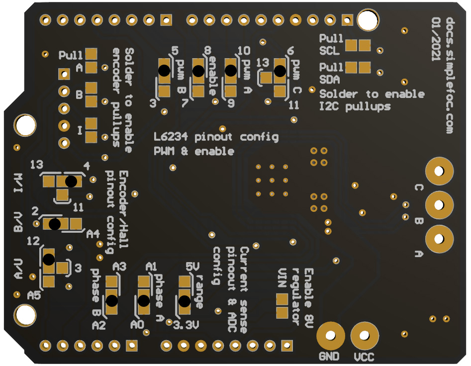
SimpleFOCShield v2
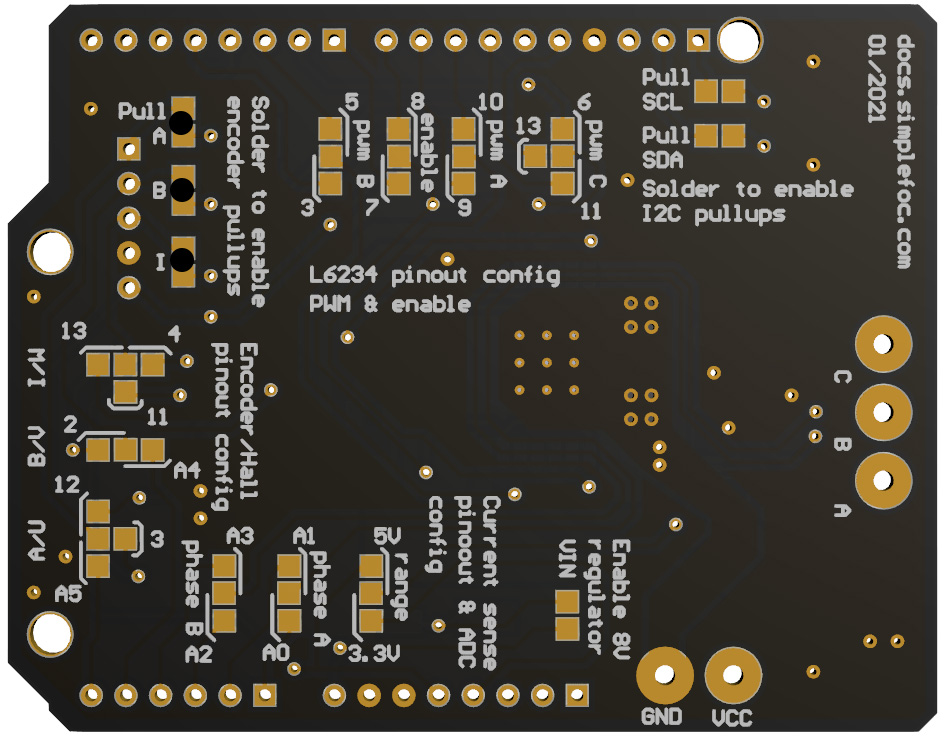
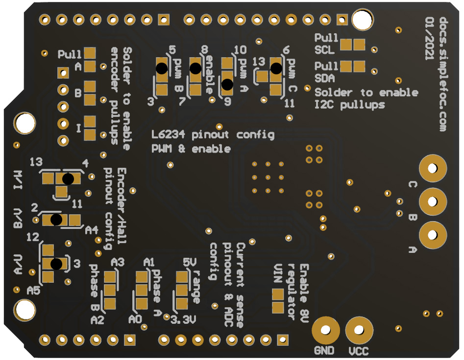
One of the very important features of the Arduino SimpleFOCShield is the hardware configuration.
Each board has a set of solder pads on the bottom side which are used for configuration. These solder pads enable board to:
- Configure BLDC driver pinout (PWM pins A,B,C and enable pin) - Read more ..
- Enable / Disable pull-up resistors for encoder A,B and Index channel - [Read more .. ](#enabling-encoderhall-sensor-pull-up-resistors
- Configure encoder/hall sensor connections - Read more ..
- Enable / Disable the linear regulator - Read more ..
- Configure the range of the ADC - Read more ..
- Configure the pinout of current sensing - Read more ..
BEWARE 📢: Conductive ink
Many Arduino SimpleFOCShield boards will be initially tested and they will be shipped with initial configuration. The testing configuration will be done with use of conductive ink instead of soldering connections. Therefore once you have the board, if you wish to change configuration all you need to do is remove the ink with some wet paper wipe.
Enabling encoder/hall sensor pull-up resistors
Each board has integrated set of three 3.3KOhm pull-up resistors for encoder channels A,B and Index (or Hall sensor U, V, W). The picture above shows how solder the pads in order to enable the Pull-up resistors. Not all encoders need the pull-up resistors, or better said, in general, most of them don’t need them. For those of us who are looking for price optimization :slight_smile: , a lot of cheap Ebay/Aliexpress encoders will need them such as 600P ebay encoder and similar.
Enabling I2C pull-up resistors
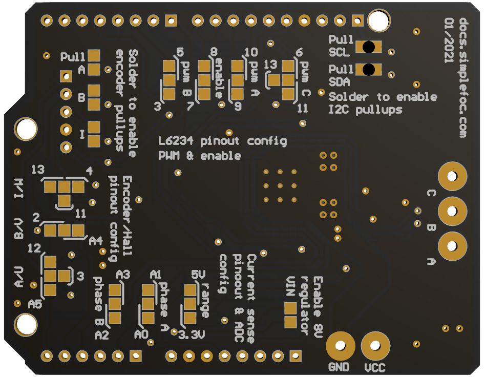
From the shield version 1.3.2 the boards come with with 4.7KOhm pull-up resistors for I2C communication pins. The picture above shows how solder the pads in order to enable the Pull-up resistors. Not all I2C devices (especially Magnetic sensors) need the pull-up resistors, or better said, in general, most of them don’t need them, especially with Arduino UNO. But it is very common to have problems interfacing these sensors with STM32 boards such as Nucleo-64. There you will need to enable the pullups or provide them yourself externally.
BEWARE: Stacking
If you are stacking the shields and you wish to use the I2C pull-ups, make sure you solder these pads on only board at a time!
Enabling on-board voltage regulator to power the MCU
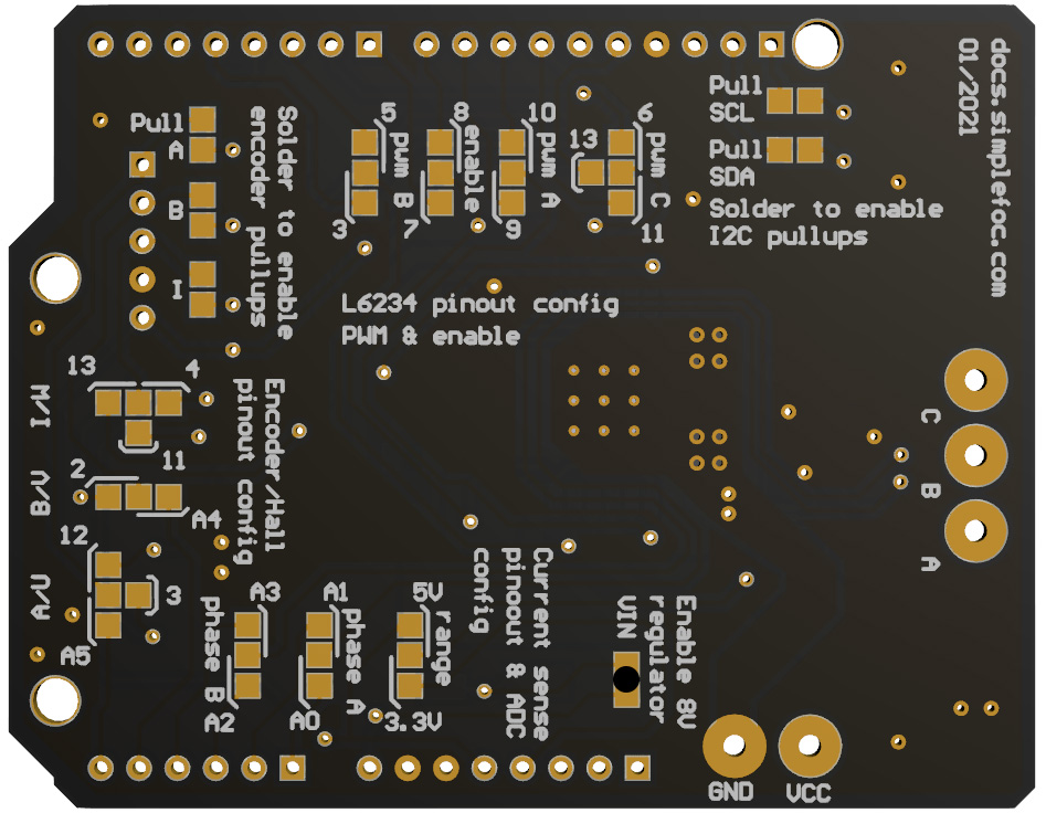
The boards from version 2.0 have integrated linear regulator in order to provide a way to power the MCU on which the board has been stacked on with power combing form boards terminals. Board version v2.0.1 has 5V regulator integrated connected directly to the 5V pin of the board which will work without any problem with all Arduino boards. But stm32 Nucleo does not support this type of power transfer therefore version v2.0.1 will not be able to power-up the Nucleo-64 board just by soldering the pad on the image above. Version v2.0.2 of the SimpleFOCShield has 8V regulator on-board connected to the VIN pin of the shield which will enable powering up the Nucleo-64 boards.
BEWARE: Stacking
If you are stacking the shields and you wish to use the linear regulator, make sure to enable it on only one board!
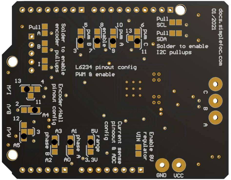
Configuring the current sensing ADC range
If your microcontroller has 5V logic the chances are that its ADC operates in 5V range nad if your mcu works on 3.3V it will most probably have a 3.3V ADC range. Please check the datasheet before soldering this pad. If the ADC range has been choses to be 3.3V the maximal current that can be measured will be 3.3A bidirectional and if the rage is 5V the maximal current will be 5V bidirectional.
RULE OF THUMB: 3.3V or 5V
Arduino UNO - 5V range
stm32 (nucleo, bluepill) and esp32 chips - 3.3V range
Configuring the current sensing pinout
The pinout of current sensing is very simple and the only real important thing is that we do not use the same pins for something else. Therefore if stacking multiple boards make sure to configure the each board in a way to use the pair of pins that the other one does not use.
| Signal | Possible pins |
|---|---|
| Current phase A | A0, A1 |
| Current phase B | A2, A3 |
📢 If not sure which pins to use, check our guide to choosing ADC pins!
Customizing pinout
Pinout customization of the SimpleFOCShield enables the board to be very flexible with using different sensors and additional arduino modules. But more importantly it enables the board to be stackable.
Here is a table of the configurable signals and their possible pin assignments:
| Signal | Possible pins |
|---|---|
| Pwm A | 9, 10 |
| Pwm B | 3, 5 |
| Pwm C | 6, 11, 13 |
| Enable | 7, 8 |
| Encoder A | 3, 12, A5 |
| Encoder B | 2, A4 |
| Encoder I | 4, 11, 13 |
Now, there is a lot of possible pin configurations and not all of them are possible depending on the microcontroller and sensor you are using. For example, Arduino UNO only has 2 external interrupt pins, and they are pin 2 and 3. Therefore when using the board with Arduino UNO and Encoder we will try to use pin 3 for encoder channel A and not for pwm A.
Another example is when stacking two boards with the STM32 Nucleo. Nucleo board cannot have pwm generation on pins 11 and 6 therefore you cannot combine those pins at the same time. Therefore whn using Nucleo board, the rule of thumb is to avoid using pin 11 but use pin 13 instead.
📢If not sure which pins to use, check our guide to choosing PWM pins!
Therefore in the following text you can find the suggested pinout configuration based on the stacking necessity and the microcontroller used.
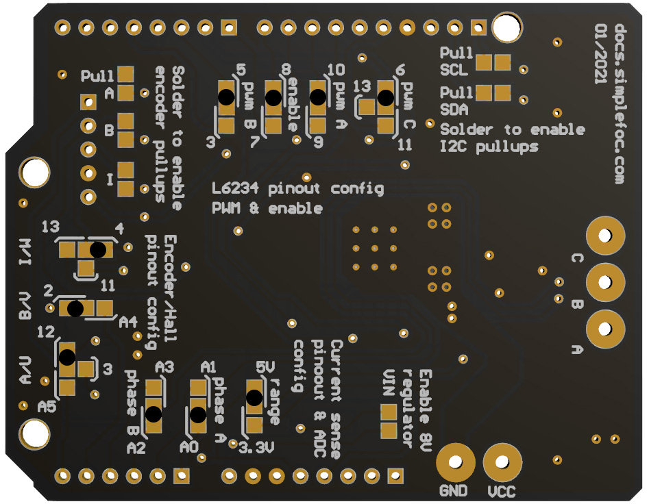
Suggested pinout: Single board
When using only one board with only one motor, it is much easier to choose the pinout. Basically you only need to be careful if you are using the encoder to use pin 3 with encoder channel A and not withe the driver’s pin pwm A. And as well, if you are using the SPI magnetic sensor you should avoid using pins 10 and 11 because they are used with the SPI communication.
With all of this in mind, probably the best pinout you can have when using one board will be:
| Signal | Pwm A | Pwm B | Pwm C | Enable | Encoder A | Encoder B | Encoder I |
|---|---|---|---|---|---|---|---|
| Pin number | 9 | 5 | 6 | 8 | 3 | 2 | 4 |
On the image above you can see which soldering pads you would need to solder in order to obtain this configuration.
// driver instance configuration based on pinout above
BLDCDriver3PWM driver = BLDCDriver3PWM(9, 5, 6, 8);
Suggested pinout: Stacking with Arduino UNO
Arduino UNO has only 6 pwm pins which means when we stack two boards we do not have much choice which ones to use, we need all of them. It is nto important how we organize the pwm A,B,C,enable and encoder A,B,I signals as log as we use pin 3 for pwm A and as long as we don’t use pin 13 for pwm C.
Here is one example of a pin assignment compatible with Arduino UNO:
| Signal | Pwm A | Pwm B | Pwm C | Enable | Encoder A | Encoder B | Encoder I |
|---|---|---|---|---|---|---|---|
| Board #1 | 10 | 5 | 6 | 8 | 12 | 2 | 4 |
| Board #2 | 9 | 3 | 11 | 7 | A5 | A4 | 13 |
The figure above shows how to solder the pads on both boards to obtain the desired pinout.
// motor instances configuration based on pinout above
BLDCDriver3PWM driver1 = BLDCDriver3PWM(10, 5, 6, 8);
BLDCDriver3PWM driver2 = BLDCDriver3PWM(9, 3, 11, 7);
Suggested pinout: Stacking with Stm32 Nucleo
When using stacked SimpleFOCShield with stm32 Nucleo board, we just have to make sure not to use pin 11 for pwm C, but to use pin 13 instead. And as for Arduino UNO, we should not use pin 3 for encoder A, but for pwm A. But if we respect these constraints we can choose the other pins as we wish.

Here is an example of chosen pinout configuration valid for stacking with Nucleo board.
| Signal | Pwm A | Pwm B | Pwm C | Enable | Encoder A | Encoder B | Encoder I |
|---|---|---|---|---|---|---|---|
| Board #1 | 10 | 5 | 6 | 8 | 12 | 2 | 4 |
| Board #2 | 9 | 3 | 13 | 7 | A5 | A4 | 11 |
See the figure above to find how to solder the pads to obtain this configuration.
// motor instances configuration based on pinout above
BLDCDriver3PWM driver1 = BLDCDriver3PWM(10, 5, 6, 8);
BLDCDriver3PWM driver2 = BLDCDriver3PWM(9, 3, 13, 7);