On this page
Measuring phase resistance
Phase resistance is a critical motor parameter required for current control and motor characterization in SimpleFOC. This guide explains what it is and how to measure it accurately.
Most of this guide has been contributed by @naikymen.
What is phase resistance?
Phase resistance (\(R_{phase}\)) is the DC resistance of a single motor winding, measured in Ohms (Ω).
Line resistance (\(R_{line}\)) is the resistance measured between two motor terminals. This differs from phase resistance depending on how the windings are connected internally.
The relationship between line and phase resistance depends on the motor’s winding configuration.
Motor types and winding configurations
Stepper motors (2-phase)
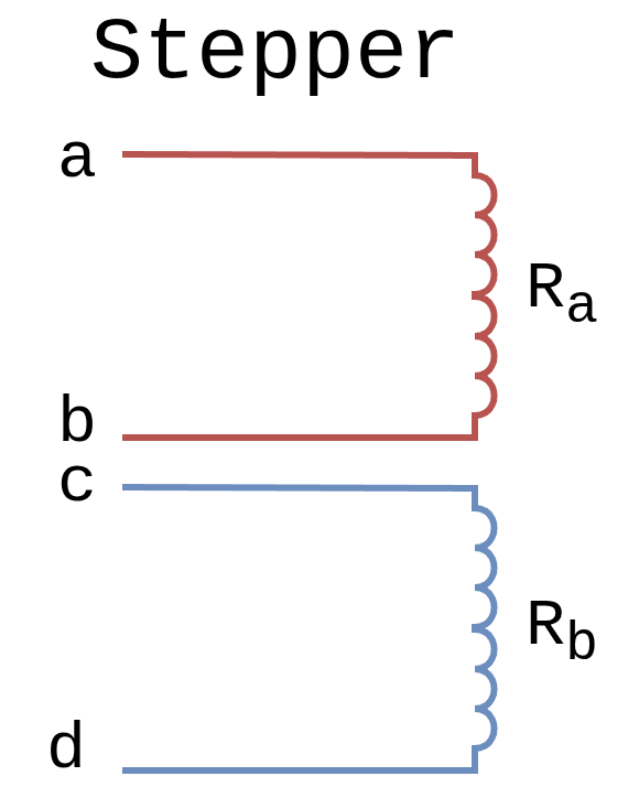
Stepper motors are the simplest case - they have 2 independent phases (A and B), typically with 4 wires.
Identifying wire pairs:
- Wires belonging to the same phase show continuity (low resistance)
- Wires from different phases show infinite resistance
Conversion factor: None - the measured line resistance equals phase resistance.
Typical values: 1-50Ω depending on motor size and voltage rating.
3-phase BLDC motors
3-phase BLDC motors use either Wye/Star or Delta winding configurations:

Common configurations for 3-phase motors (source).
3-wire Wye/Star

- Wires: 3 phase terminals only (center point internal)
- Line resistance: Two windings in series through center point
- Conversion factor: \(R_{phase} = \frac{R_{line}}{2}\)
4-wire Wye/Star

- Wires: 3 phase terminals + 1 center point (neutral)
- Identifying center point: Shows half the resistance to all other wires
- Conversion factor: None when measuring center-to-phase (\(R_{phase} = R_{line}\))
3-wire Delta

- Wires: 3 phase terminals only
- Line resistance: One winding in parallel with two in series
- Conversion factor: \(R_{phase} = R_{line} \times 1.5\)
Identifying your 3-phase BLDC configuration
- Count the leads:
- 4 wires → Wye/Star with center point
- 3 wires → Wye/Star (no center) or Delta
- For 4-wire motors:
- Measure all pairs - the wire with half the resistance to all others is the center point
- For 3-wire motors:
- Check datasheet, or
- Measure and compare to typical resistance ranges
- If all pairs equal, could be either - try both conversion factors and check which gives reasonable value
Measurement methods
Two methods are available depending on your available equipment:
- Multimeter method - Direct resistance measurement (simplest)
- Voltage-current method - Ohm’s law with power supply (more accurate for low resistance)
Method 1: Multimeter resistance measurement
The simplest method using a standard multimeter in resistance (Ω) mode.
For Stepper motors
Procedure:
- Set multimeter to resistance (Ω) mode
- Test all wire pair combinations to identify phases:
- Same phase: Low resistance (1-50Ω typical)
- Different phases: Infinite resistance (open circuit)
- Measure resistance across each identified phase pair
- Both phases should show similar values (within 10%)
Result: The measured value is directly the phase resistance (no conversion needed).
For 3-wire Wye/Star BLDC
Procedure:
- Measure resistance across any pair of leads
- Verify all three pairs show the same resistance (line resistance)
- Divide by 2 to get phase resistance: \(R_{phase} = \frac{R_{line}}{2}\)
For 4-wire Wye/Star BLDC
Procedure:
- Identify center point: Measure all pairs - the wire showing half the resistance to all others is the center
- Measure from center to any phase lead
Result: This is directly the phase resistance (no conversion needed).
For 3-wire Delta BLDC
Procedure:
- Measure resistance across any pair of leads
- Verify all three pairs show equal resistance (line resistance)
- Multiply by 1.5 to get phase resistance: \(R_{phase} = R_{line} \times 1.5\)
Method 2: Voltage-current measurement
For more accurate measurements, especially with low-resistance motors (< 1Ω), use a voltage source and measure current.
Equipment needed:
- Adjustable DC power supply (or battery + voltmeter)
- Ammeter (or power supply with current display)
Procedure (all motor types)
- Apply low DC voltage (1-2V) across appropriate motor leads:
- Stepper: Across one phase pair
- 3-wire BLDC: Across any two phase leads
- 4-wire Wye BLDC: Between center and one phase lead
- Wait for steady state (few milliseconds for inductive transient to settle)
- Measure steady-state current (in amps)
- Calculate line resistance: \(R_{line} = \frac{U_{applied}}{I_{measured}}\)
- Convert to phase resistance using configuration factor:
- Stepper: \(R_{phase} = R_{line}\) (no conversion)
- 3-wire Wye/Star: \(R_{phase} = \frac{R_{line}}{2}\)
- 4-wire Wye/Star (center-to-phase): \(R_{phase} = R_{line}\) (no conversion)
- 3-wire Delta: \(R_{phase} = R_{line} \times 1.5\)
Safety and accuracy tips
Before applying voltage:
- Estimate expected current: \(I_{expected} = \frac{U_{applied}}{R_{estimated}}\)
- Start with low voltage (1-2V) to avoid excessive current
- Ensure current won’t exceed motor ratings or power supply limits
During measurement:
- Wait for steady state before reading current (inductive transient settles in ~1-10ms)
- Ensure motor is at room temperature (resistance changes ~0.4% per °C for copper)
- Use DC voltage, not PWM (or use very low frequency < 100Hz)
When to use this method:
- Motor resistance < 1Ω (multimeter accuracy insufficient)
- Need 4-wire Kelvin measurement for very low resistance
- Verifying resistance under actual driver operation
Example calculation
Motor: 3-wire Wye configuration, estimated \(R_{phase} \approx 1\Omega\)
Measurement:
- Apply 2V across two phase leads
- Measure current: 1.0A
- Calculate line resistance: \(R_{line} = \frac{2V}{1.0A} = 2\Omega\)
- Convert to phase (Wye): \(R_{phase} = \frac{2\Omega}{2} = 1\Omega\)
Verification: Expected current was \(I = \frac{2V}{2\Omega} = 1A\) ✓