On this page
Coordinate Transformations in FOC v2.4+
Field Oriented Control (FOC) is a mathematical technique that transforms the control of BLDC and stepper motors into the equivalent of controlling a DC motor. This page explains the mathematical foundations of FOC, focusing on the coordinate transformations and principles that enable precise torque control.
The FOC principle: Electromagnetic force maximization
FOC ensures that the magnetic field generated by the stator windings is always positioned 90° ahead of (perpendicular to) the rotor’s permanent magnetic field.

This 90° relationship maximizes electromagnetic force according to Lorentz force law:
\[\vec{F} = \int (\vec{I} \times \vec{B}) \, dL\]For a conductor carrying current \(I\) in a magnetic field \(B\), the force magnitude is:
\[F = B \cdot I \cdot L \cdot \sin(\theta)\]Where:
- \(B\) = magnetic field strength (Tesla)
- \(I\) = current magnitude (Amperes)
- \(L\) = effective conductor length (meters)
- \(\theta\) = angle between magnetic field and current direction
Maximum force condition: \(F_{max} = B \cdot I \cdot L\) occurs when \(\theta = 90°\) since \(\sin(90°) = 1\).
Torque generation
For a motor with radius \(r\), the torque is:
\[\tau = r \cdot F = r \cdot B \cdot I \cdot L = K_t \cdot I\]By maintaining the 90° relationship between stator field and rotor flux, FOC ensures maximum torque per amp, and (\(\tau = K_t \cdot I\)) is achieved at all rotor positions.
Comparison with DC motors
In DC motors, brushes and commutator mechanically maintain this 90° relationship:
- Brushes switch current direction as rotor rotates
- Commutator segments ensure field alignment is always optimal
- Automatic 90° relationship without computation
FOC achieves the same result electronically through mathematical transformations:
- Rotor position sensor provides \(\theta_{el}\)
- Coordinate transforms calculate required phase currents/voltages
- Inverter applies calculated voltages
- Result: AC motor controlled like DC motor, but without mechanical wear
Six-step commutation visualization showing rotating magnetic field synchronized with rotor
Coordinate transformations: The mathematical core
FOC uses multiple reference frames to simplify motor control. The key insight is that controlling currents in a rotating reference frame (that follows the rotor) is much simpler than controlling them in the stationary frame (fixed to the stator).
Reference frames
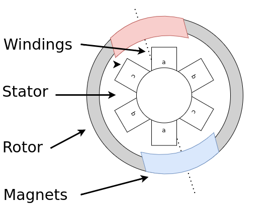
Each motor winding a,b,c (or stepper a and b) can produce a magnetic field vector in the stationary direction. Each of the directions is 120° apart from each other (stepper 90° apart). The motor rotor has permanent magnets that generate stationary magnetic field which is rotating with the rotor and at any give point is \(\theta\) degrees apart from the phase a magnetic field. See the figure below for a visualisation of the different reference frames.
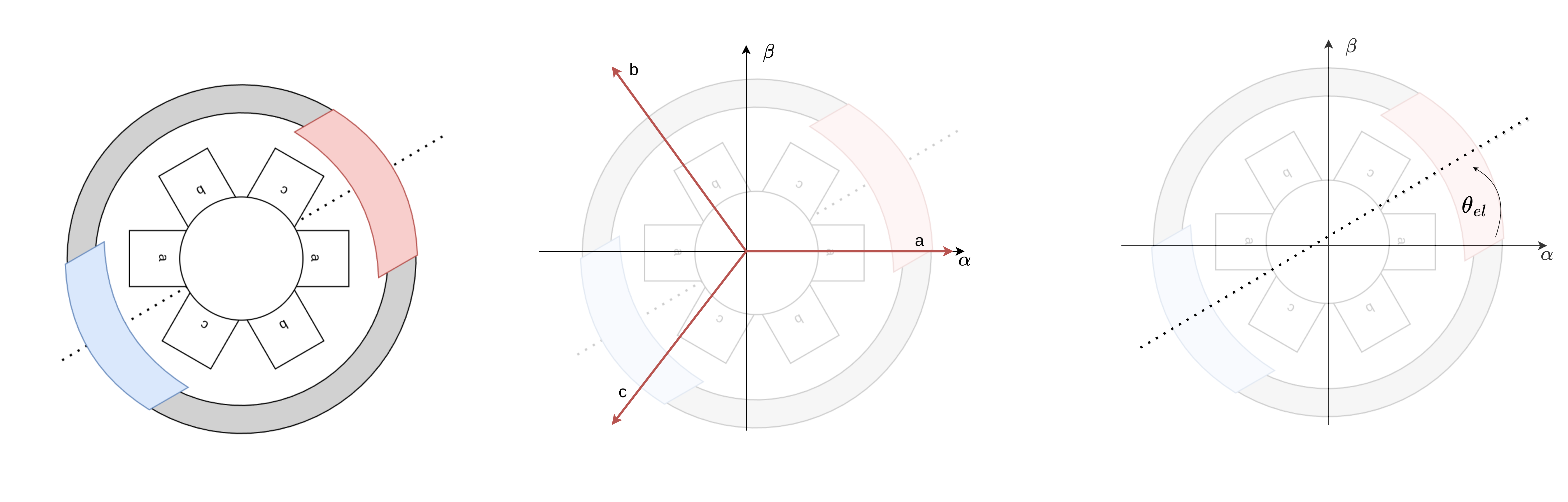
Then we can define three different reference frames that will be used in the FOC control. One signle current vector with magnitude \(I\) and angle \(\theta\) can be represented in any of them. See the image below.
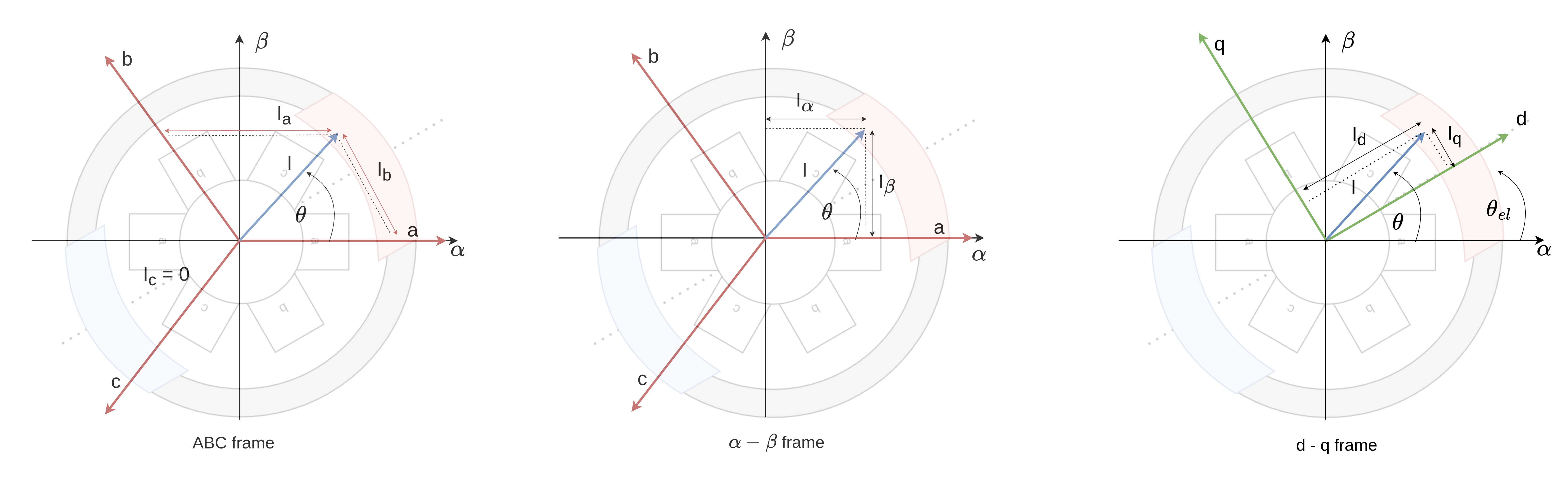
1. Stationary frame (abc):
- Fixed to the stator
- Three phase voltages/currents: \(u_a, u_b, u_c\) or \(i_a, i_b, i_c\)
- Time-varying sinusoids at electrical frequency \(\omega_e\)
2. Stationary orthogonal frame (\(\theta\)-\(\beta\)):
- Also fixed to the stator
- Two orthogonal components: \(u_\theta, u_\beta\) or \(i_\theta, i_\beta\)
- Clarke Transform converts abc → \(\theta\beta\)
- Still time-varying
3. Rotating frame (d-q):
- Rotates with the rotor at \(\omega_e\)
- Two components: \(u_d, u_q\) or \(i_d, i_q\)
- Park Transform converts \(\theta\beta\) → dq
- DC values when synchronized with rotor
- Enables simple PI control
The d-q reference frame
In the d-q frame rotating at electrical angle \(\theta_{el}\):
- d-axis (direct): Aligned with rotor flux (permanent magnet field)
- q-axis (quadrature): Perpendicular to rotor flux (90° ahead)
Key property: For maximum torque efficiency: \(i_d = 0, \quad i_q = \frac{\tau}{K_t}\)
This means:
- \(i_d = 0\): No current wasted on flux (permanent magnets provide it)
- \(i_q\): All current produces torque
Clarke Transform (abc → \(\theta\beta\))
Converts three-phase quantities to two-phase orthogonal components:
For balanced three-phase systems:
\[\begin{bmatrix} i_\theta \\ i_\beta \end{bmatrix} = \frac{2}{3} \begin{bmatrix} 1 & -\frac{1}{2} & -\frac{1}{2} \\ 0 & \frac{\sqrt{3}}{2} & -\frac{\sqrt{3}}{2} \end{bmatrix} \begin{bmatrix} i_a \\ i_b \\ i_c \end{bmatrix}\]Expanded:
\[\begin{align} i_\theta &= \frac{2}{3} \left( i_a - \frac{1}{2}i_b - \frac{1}{2}i_c \right) = i_a \\ i_\beta &= \frac{2}{3} \left( \frac{\sqrt{3}}{2}i_b - \frac{\sqrt{3}}{2}i_c \right) = \frac{1}{\sqrt{3}}(i_b - i_c) \end{align}\]Using \(i_a + i_b + i_c = 0\) (Kirchhoff’s law), this simplifies to:
\[\begin{align} i_\theta &= i_a \\ i_\beta &= \frac{1}{\sqrt{3}}(i_b - i_c) = \frac{1}{\sqrt{3}}(i_b + i_a + i_b) = \frac{2i_b + i_a}{\sqrt{3}} \end{align}\]Geometric interpretation: Projects three 120° spaced vectors onto two orthogonal axes.
Park Transform (\(\theta\beta\) → dq)
Rotates the stationary \(\theta\)-\(\beta\) frame to align with the rotor:
\[\begin{bmatrix} i_d \\ i_q \end{bmatrix} = \begin{bmatrix} \cos(\theta_{el}) & \sin(\theta_{el}) \\ -\sin(\theta_{el}) & \cos(\theta_{el}) \end{bmatrix} \begin{bmatrix} i_\theta \\ i_\beta \end{bmatrix}\]Expanded:
\[\begin{align} i_d &= i_\theta \cos(\theta_{el}) + i_\beta \sin(\theta_{el}) \\ i_q &= -i_\theta \sin(\theta_{el}) + i_\beta \cos(\theta_{el}) \end{align}\]Result: Time-varying AC currents (\(i_\theta, i_\beta\)) become DC currents (\(i_d, i_q\)) in the rotating frame, making PI control straightforward.
Inverse transformations: From control to actuation
FOC control operates in the d-q frame, but the motor requires phase voltages. The inverse transforms convert back:
Inverse Park Transform (dq → \(\theta\beta\))
\[\begin{bmatrix} u_\theta \\ u_\beta \end{bmatrix} = \begin{bmatrix} \cos(\theta_{el}) & -\sin(\theta_{el}) \\ \sin(\theta_{el}) & \cos(\theta_{el}) \end{bmatrix} \begin{bmatrix} u_d \\ u_q \end{bmatrix}\]Expanded:
\[\begin{align} u_\theta &= u_d \cos(\theta_{el}) - u_q \sin(\theta_{el}) \\ u_\beta &= u_d \sin(\theta_{el}) + u_q \cos(\theta_{el}) \end{align}\]This is a rotation matrix that converts the DC voltages (\(u_d, u_q\)) back to the stationary frame.
Inverse Clarke Transform (\(\theta\beta\) → abc)
For 3-phase BLDC motors:
\[\begin{bmatrix} u_a \\ u_b \\ u_c \end{bmatrix} = \begin{bmatrix} 1 & 0 \\ -\frac{1}{2} & \frac{\sqrt{3}}{2} \\ -\frac{1}{2} & -\frac{\sqrt{3}}{2} \end{bmatrix} \begin{bmatrix} u_\theta \\ u_\beta \end{bmatrix}\]Expanded:
\[\begin{align} u_a &= u_\theta \\ u_b &= -\frac{1}{2} u_\theta + \frac{\sqrt{3}}{2} u_\beta \\ u_c &= -\frac{1}{2} u_\theta - \frac{\sqrt{3}}{2} u_\beta \end{align}\]For 2-phase stepper motors, no Clarke transform is needed:
\[\begin{align} u_a &= u_\theta = u_d \cos(\theta_{el}) - u_q \sin(\theta_{el}) \\ u_b &= u_\beta = u_d \sin(\theta_{el}) + u_q \cos(\theta_{el}) \end{align}\]The two phases are already in the \(\theta\)-\(\beta\) frame.
Motor-specific implementations
BLDC motors (3-phase)
- Transformations: Full chain (Park → Clarke → 3 phases)
- Equations: Use \(u_d, u_q \to u_\theta, u_\beta \to u_a, u_b, u_c\)
- Driver: 3-phase PWM driver
Stepper motors (2-phase)
- Transformations: Park only (\(u_d, u_q \to u_a, u_b\))
- Equations: No Clarke needed (already orthogonal)
- Driver: 2-phase PWM driver
- Note: \(\theta\)-\(\beta\) frame coincides with physical phases A-B
Hybrid stepper motors
- Transformations: Full chain like BLDC
- Driver: 3-phase BLDC driver (phase C as mid-point reference)
- Special: Phase C typically held at \(V_{supply}/2\) in SinePWM mode
Further reading
- PWM Modulation Strategies - SinePWM, SVPWM, trapezoidal modulation
- Voltage-based torque control theory - D-Q frame dynamics and motor equations
- Estimated current control - Using motor parameters for improved control
- FOC implementation source code - Detailed code walkthrough
- Motor configuration - Setting up motors and tuning parameters