On this page
Torque control using FOC currents
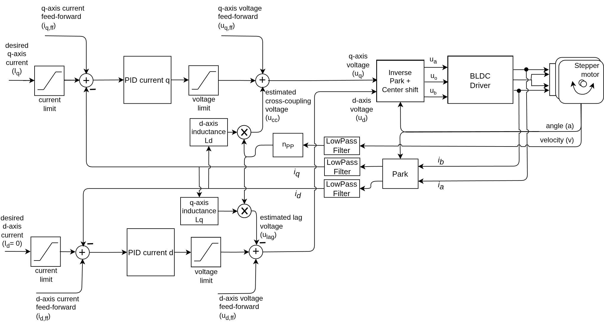
BLDC motors Stepper motors Hybrid Stepper motors
This torque control mode allows you to the true torque control of BLDC and stepper motors. This technique relies on a combination of position and current sensing to rotate the magnetic field vector of the stator in sync with the rotor magnetic field and procude optimal and smooth motor torque.
// FOC current torque control mode
motor.torque_controller = TorqueControlType::foc_current;
How does it work exactly
BLDC motors Stepper motors Hybrid Stepper motors
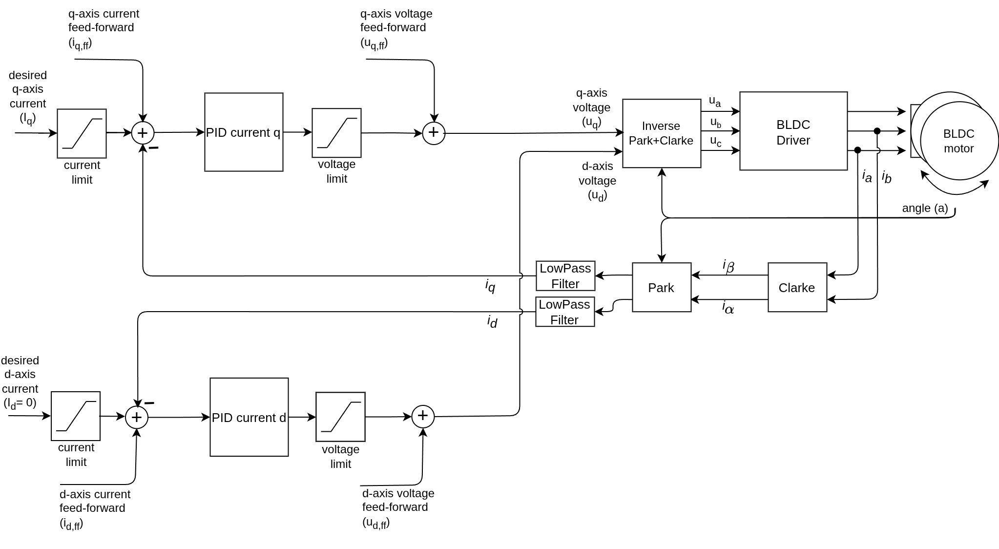
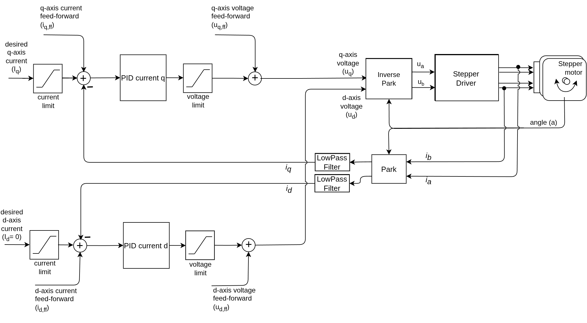
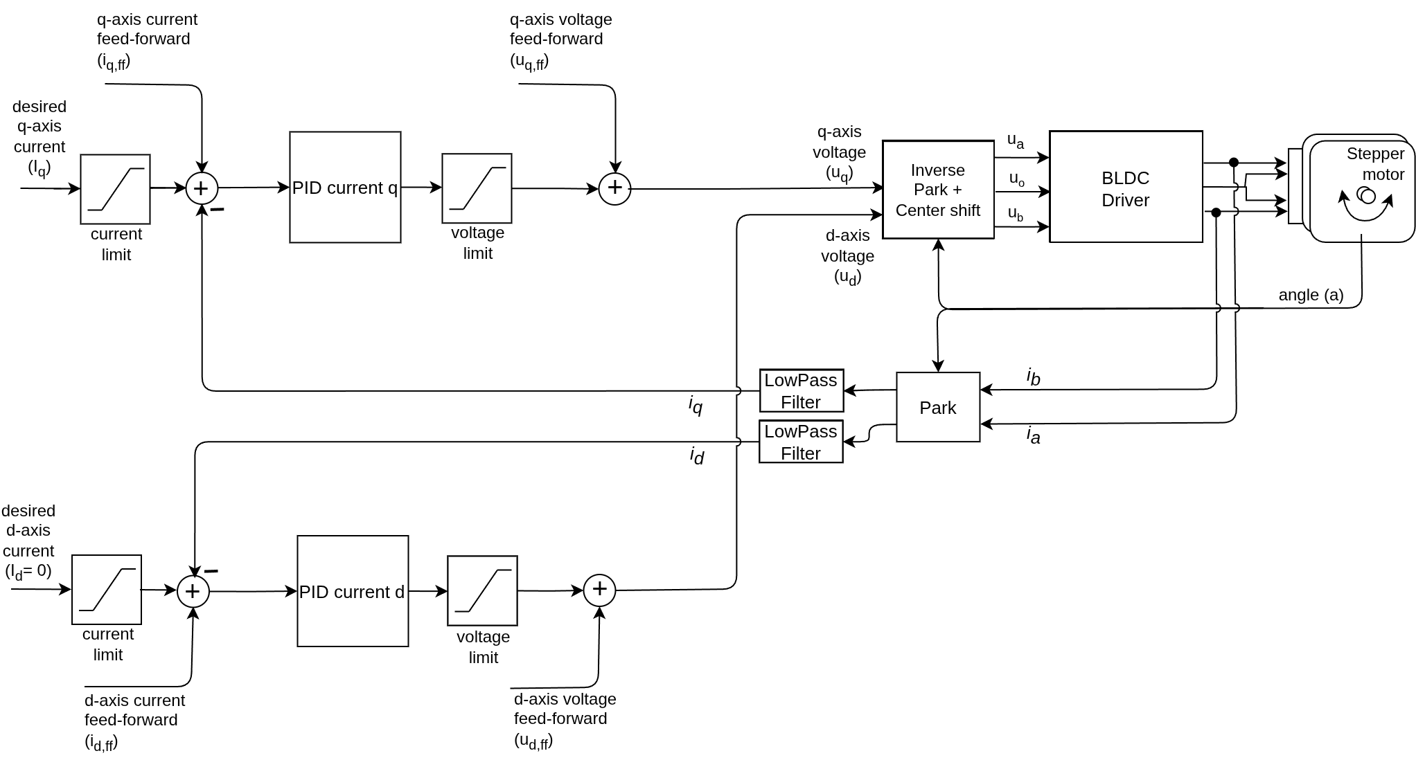
FOC control consists in two control loop, one per d-q axis. The q-axis is responsible for controlling the torque of the motor, while the d-axis is responsible for controlling the magnetic flux. Since the magnetic flux of the rotor is constant and produced by the permanent magnets, the d-axis current is typically set to zero.
In this control mode the user sets the target q-axis current \(i_q\) and the FOC algorithm calculates the appropriate q-axis voltage to be applied to the motor to maintain the desired current \(u_q\). Instead of relying on the motor model (link in estimated current control), the FOC control measures the motor phase currents and closes the control loops using PID controllers. This approach is much more robust and less prone to parameter inaccuracies, but it requires a current sensor to be implemented in the system.
The control law for the q-axis voltage is:
\[u_q = \text{PI}_q(i_q - \hat{i}_q)\]Where \(\hat{i}_q\) is the measured q-axis current, which is calculated from the phase currents using the Clarke and Park transformations.
The d-axis voltage is calculated in a similar way, but since the target d-axis current is typically set to zero, the control law simplifies to:
\[u_d = \text{PI}_d(i_d - \hat{i}_d), \quad \text{with } i_d = 0, \quad u_d = \text{PI}_d(-\hat{i}_d)\]By measuring and controlling the currents in the d and q-axis, the FOC algorithm is able to maintain optimal torque production and smooth motor operation over a wide speed range, and intrinsically compensate for the back-EMF voltage, inductive lag, and other non-linearities of the motor, without relying on a motor model.
As the measured \(\hat{i}_q\) and the target \(i_q\) are controlled to be equal, the real torque produced by the motor is directly proportional to the target q-axis current, according to the following formula:
\[\hat{\tau} = K_t \hat{i}_q = K_t i_q = \tau\]See a deeper dive in motor dynamics and FOC control teory See a deeper dive in the FOC transformations theory
Cross-coupling and lag compensation (Advanced)
BLDC motors Stepper motors Hybrid Stepper motors
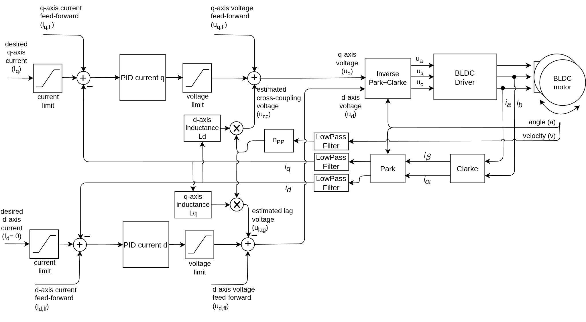
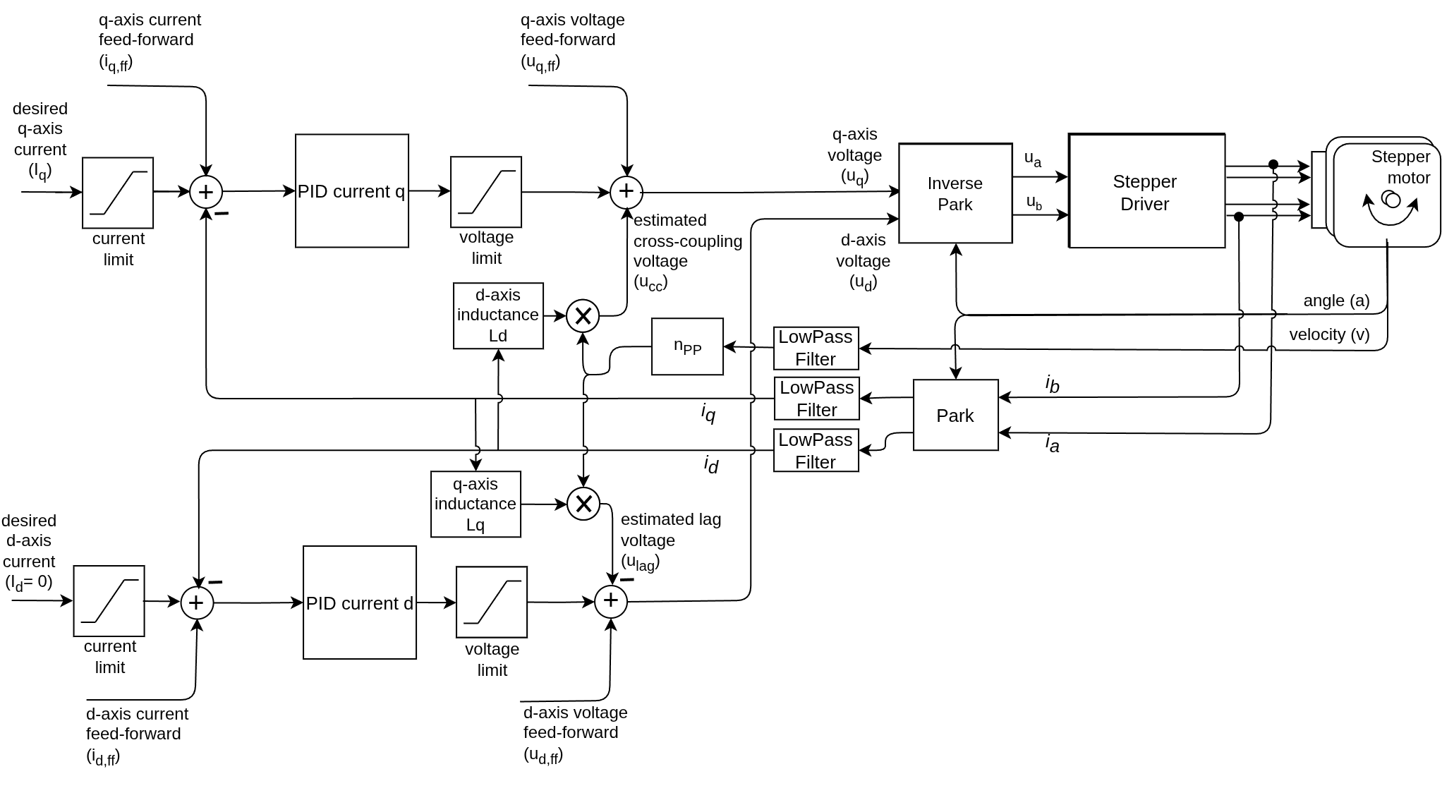
If the user provides motor parameters such as phase inductances (\(L_d, L_q\)), the library can also compensate for the cross-coupling between d and q-axis and for the inductive lag, by adding feed-forward terms to the control law:
\[\begin{aligned} u_q &= \text{PI}_q(i_q - \hat{i}_q) + L_d i_d v_e \\ u_d &= \text{PI}_d(- \hat{i}_d) - L_q i_q v_e \end{aligned}\]Where \(v_e\) is the electrical angular velocity of the motor \(v_e = n_{pp} \cdot v\), with \(n_{pp}\) being the number of pole pairs and \(v\) the mechanical angular velocity of the rotor.
It is worth noting that in steady-state (when PI controllers stabilise) the cross-coupling and inductive lag will be compensated even without the feed-forward terms. However, at highly dynamic conditions and at high speeds, the PI controllers alone may not be able to keep up with the rapidly changing currents, and the feed-forward compensation can significantly improve the performance of the torque control.
To enable this mode provide the phase inductance values in the motor constructor or by setting the parameters directly:
motor.axis_inductance.q = L_q; // set q-axis inductance
motor.axis_inductance.d = L_d; // set d-axis inductance (if not set only L_q will be used for compensation)
See a deeper dive in motor dynamics and FOC control teory
Configuration & Tuning
To make this loop run smoothly, you must configure the PID controllers for both axes. In current control, the I-gain is often much higher than in velocity or position loops because current reacts almost instantly.
| Parameter | Attribute | Typical Range | Description |
|---|---|---|---|
| P Gain | PID_current_q/d.P | $2.0 - 20.0$ | Immediate response to current error. |
| I Gain | PID_current_q/d.I | $300 - 5000$ | Eliminates steady-state error. Crucial for BEMF compensation. |
| Filter | LPF_current_q/d.Tf | $0.0001 - 0.01$ | Smooths noisy current readings. Lower is faster but noisier. |
// Example: Setting parameters for the Q axis
motor.PID_current_q.P = 5.0;
motor.PID_current_q.I = 1000.0;
motor.LPF_current_q.Tf = 0.005;

// D axis parameters should usually match the Q axis
motor.PID_current_d.P = 5.0;
motor.PID_current_d.I = 1000.0;
motor.LPF_current_d.Tf = 0.005;
💡 Tip: Use Auto-Tuning
If you know your motor’s Phase Resistance (\(R\)) and Inductance (\(L\)), the library can calculate these PID gains for you! These two parameters are the “sweet spot” for performance—easy to measure and massive in their impact.
Learn about Parameter Measurement Learn about Current Auto-tuning
Targets, Limits and Feed-forward
The FOC current torque control mode allows you to set the target current \(i_q\) directly, which is proportional to the torque generated by the motor. The current is specified in Amperes and is communicated to the torque control loop from the motion control loop through the current_sp variable of the motor object, for example:
motor.current_sp = 0.5; // set target current to 0.5 A
This varaible is set internally in the FOCMotor object and should not be modified by the user. If one wants to control the torque of the motor, they should use the motion control mode torque and set the target variable.
motor.torque_controller = TorqueControlType::foc_current;
motor.controller = MotionControlType::torque;
motor.target = 0.5; // set target torque to 0.5 Amp
This current contol mode aloows the user to specify the hard limits for the d and q-axis currents, which will be applied by the torque control loop. For example, if you want to limit the current to 1 A, you can set:
motor.current_limit = 1.0; // set current limit to 1 A
as well as for the d and q-axis voltages to prevent the controller from applying too high voltages to the motor:
motor.voltage_limit = 6.0; // set voltage limit to 6 V
The prefered way of setting these values is using the setter functions
motor.updateCurrentLimit(1.0); // set current limit to 1 A
motor.updateVoltageLimit(6.0); // set voltage limit to 6 V
The library additionally allows the user to specify a feed-forward voltage and current terms for both d and q-axis, which will be added to the control law. This is an advanced feature that can be used to improve the performance of the torque control in some applications, for example to compensate for the gravity load in a robotic arm. The feed-forward terms can be set as follows:
motor.feed_forward_voltage.q = 0.5; // set q-axis voltage feed-forward to 0.5 V
motor.feed_forward_voltage.d = 0.2; // set d-axis voltage feed-forward to 0.2 V

motor.feed_forward_current.q = 0.1; // set q-axis current feed-forward to 0.1 A
motor.feed_forward_current.d = 0.05; // set d-axis current feed-forward to 0.05 A
Performance Requirements
FOC Current mode is computationally heavy. There are a couple main reasons for this:
- The mathematics behind Parke and Clarke transforms is computationally intensive, especially for low-end MCU with no floating point unit.
- Current sensing is required. This means that the MCU needs a very high sampling frequency MCU which is not always the case.
- The control loop has to run at a very high frequency (at least 1 kHz, but ideally 5-10 kHz) to maintain stable current control, which can be challenging for low-end MCUs.
With all these factors in mind, it is recommended to use a more powerful MCU: stm32, Teensy or esp32. They have relatively higher clock speeds, efficient ADCs and in some cases even integrated floating point units, which can handle the computational load of FOC current control mode.
For lower end MCUs, such as atmega328 or atmega2560 based boards, it is still possible to run FOC current control mode, but the performance may be limited. Another alternative would be to use the estimated current control mode, which is less computationally intensive and does not require a current sensor, but it is less accurate and robust than the FOC current control mode. Or if current limiting is the main concern, the DC current control mode can be used, which is a simpler current control mode that does not require the Parke and Clarke transforms, but it is less efficient and smooth than the FOC current control mode.
Torque control example code
BLDC motors Stepper motors Hybrid Stepper motors
A simple example of the FOC current based torque control using Inline current sensor and setting the target value by serial command interface.
#include <SimpleFOC.h>
// BLDC motor & driver instance
BLDCMotor motor = BLDCMotor(11);
BLDCDriver3PWM driver = BLDCDriver3PWM(9, 5, 6, 8);
// encoder instance
Encoder encoder = Encoder(2, 3, 500);
// channel A and B callbacks
void doA(){encoder.handleA();}
void doB(){encoder.handleB();}
// current sensor
InlineCurrentSense current_sense = InlineCurrentSense(0.01, 50.0, A0, A2);
// instantiate the commander
Commander command = Commander(Serial);
void doTarget(char* cmd) { command.scalar(&motor.target, cmd); }
void setup() {
// initialize encoder sensor hardware
encoder.init();
encoder.enableInterrupts(doA, doB);
// link the motor to the sensor
motor.linkSensor(&encoder);
// driver config
// power supply voltage [V]
driver.voltage_power_supply = 12;
driver.init();
// link driver
motor.linkDriver(&driver);
// link the driver to the current sense
current_sense.linkDriver(&driver);
// current sense init hardware
current_sense.init();
// link the current sense to the motor
motor.linkCurrentSense(¤t_sense);
// set torque mode:
motor.torque_controller = TorqueControlType::foc_current;
// set motion control loop to be used
motor.controller = MotionControlType::torque;
// foc current control parameters
motor.PID_current_q.P = 5;
motor.PID_current_q.I= 300;
motor.PID_current_d.P= 5;
motor.PID_current_d.I = 300;
motor.LPF_current_q.Tf = 0.01;
motor.LPF_current_d.Tf = 0.01;
// use monitoring with serial
Serial.begin(115200);
// comment out if not needed
motor.useMonitoring(Serial);
// initialize motor
motor.init();
// align sensor and start FOC
motor.initFOC();
// add target command T
command.add('T', doTarget, "target current");
Serial.println(F("Motor ready."));
Serial.println(F("Set the target current using serial terminal:"));
_delay(1000);
}
void loop() {
// main FOC algorithm function
motor.loopFOC();
// Motion control function
motor.move();
// user communication
command.run();
}