On this page
FOC Algorithm Workflow v2.4.0
The SimpleFOClibrary implements multiple FOC modulation algorithms. This section covers the implementation details about the FOC implementation in this library, so that you can better understand what is under the hood and how to change it and adapt for your application.
BLDC motors Stepper motors Hybrid Stepper motors
The implementation of the FOC algorithm in the library is based on the following key functions:
setPhaseVoltage(): Function implementing the FOC PWM modulation algorithms (Motor type specific)- See PWM modulation implementation section for details
initFOC(): Initializes the FOC algorithm and performs and verifies the sensor, motor and current sense alignment- See Motor and Sensor Alignment section for details
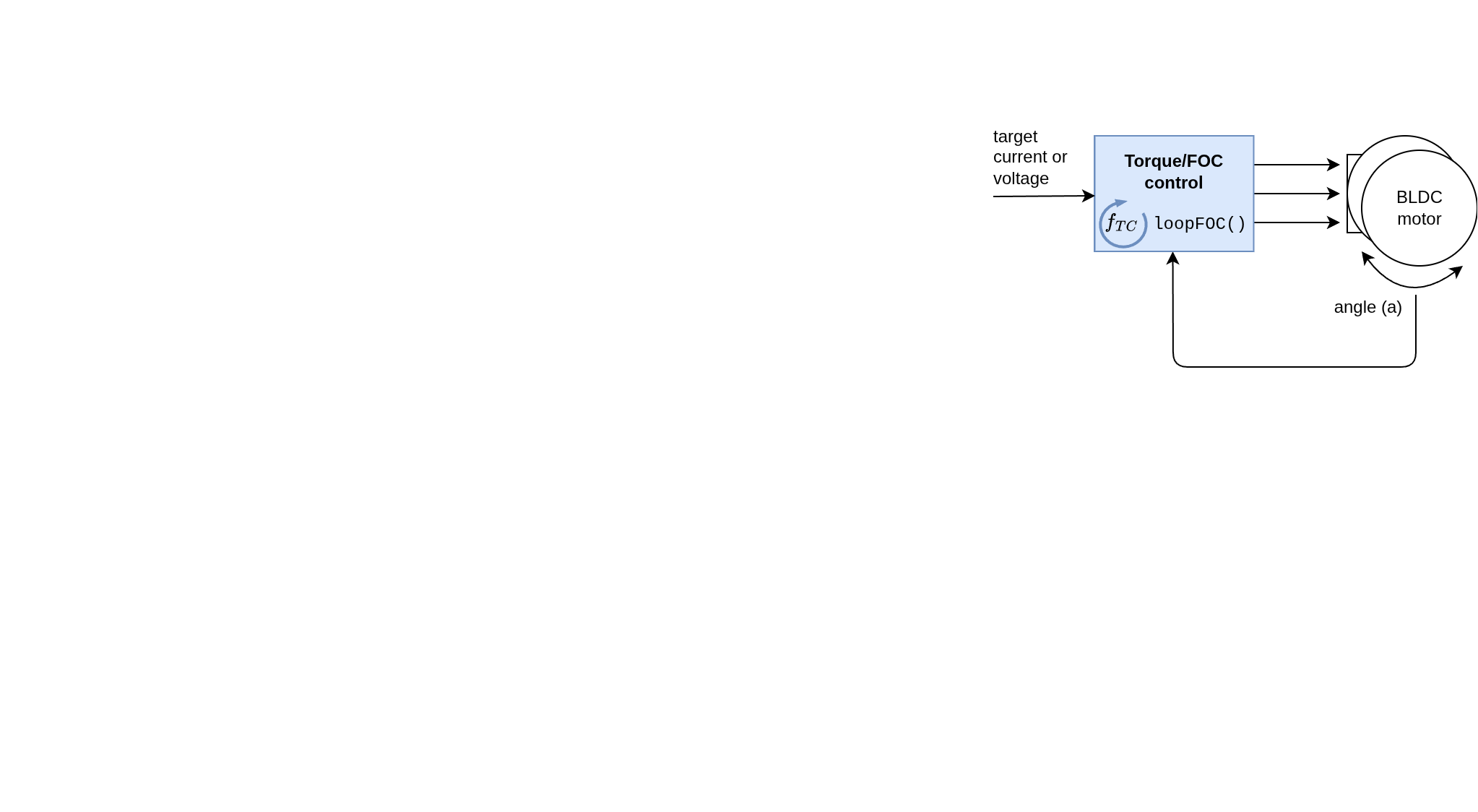
loopFOC(): The real-time torque control loop that uses FOC and continuously updates the field vector based on the selected torque control mode (voltage or current control)- See Real-Time Execution section for details
Now let’s discuss the implementation details of all three components!
PWM modulation implementation: setPhaseVoltage()
This function is motor type specific, and each motor type has its own implementation of the setPhaseVoltage() function, which is responsible for calculating the appropriate phase voltages based on the selected FOC modulation type and the desired Uq and Ud voltages.
In the case of BLDC motors, the library supports four modulation types:
- Sinusoidal PWM:
SinePWM(default) - Space Vector PWM:
SpaceVectorPWM - Trapezoidal 120°:
Trapezoid_120 - Trapezoidal 150°:
Trapezoid_150
For stepper motors the library implements
- Sinusoidal PWM:
SinePWM(default)
For hybrid stepper motors the library implements
- Sinusoidal PWM:
SinePWM(default) - Space Vector PWM:
SpaceVectorPWM
The configuration of the modulation type is done by setting the foc_modulation member variable of the motor object:
motor.foc_modulation = FOCModulationType::SinePWM; // default
// or
motor.foc_modulation = FOCModulationType::SpaceVectorPWM;
// or
motor.foc_modulation = FOCModulationType::Trapezoid_120;
// or
motor.foc_modulation = FOCModulationType::Trapezoid_150;
NOTE:
For more info about the FOC algorithm theory visit FOC theory corner.
All modulation algorithms are implemented in the setPhaseVoltage() function, which now takes both Uq (torque-producing voltage) and Ud (flux-producing voltage) parameters. The implementation is motor-type specific.
Choose your motor type:
BLDC motors Stepper motors Hybrid Stepper motors
BLDC Motor Implementation
BLDC motors use a 3-phase driver and support four different modulation types:
// Method using FOC to set Uq and Ud to the motor at the optimal angle
// Function implementing Space Vector PWM, Sine PWM and Trapezoidal commutation algorithms
void BLDCMotor::setPhaseVoltage(float Uq, float Ud, float angle_el) {
  float center;
  int sector;
  float _ca, _sa;

  switch (foc_modulation) {
    case FOCModulationType::Trapezoid_120:
      // 6-step trapezoidal commutation (120° conduction)
      sector = 6 * (_normalizeAngle(angle_el + _PI_6) / _2PI);
      center = modulation_centered ? (driver->voltage_limit)/2 : Uq;

      // Set phase voltages based on sector and high-impedance states
      if(trap_120_map[sector][0] == _HIGH_IMPEDANCE) {
        Ua = center;
        Ub = trap_120_map[sector][1] * Uq + center;
        Uc = trap_120_map[sector][2] * Uq + center;
        driver->setPhaseState(PhaseState::PHASE_OFF, PhaseState::PHASE_ON, PhaseState::PHASE_ON);
      } else if(trap_120_map[sector][1] == _HIGH_IMPEDANCE) {
        Ua = trap_120_map[sector][0] * Uq + center;
        Ub = center;
        Uc = trap_120_map[sector][2] * Uq + center;
        driver->setPhaseState(PhaseState::PHASE_ON, PhaseState::PHASE_OFF, PhaseState::PHASE_ON);
      } else {
        Ua = trap_120_map[sector][0] * Uq + center;
        Ub = trap_120_map[sector][1] * Uq + center;
        Uc = center;
        driver->setPhaseState(PhaseState::PHASE_ON, PhaseState::PHASE_ON, PhaseState::PHASE_OFF);
      }
      break;

    case FOCModulationType::Trapezoid_150:
      // 12-step trapezoidal commutation (150° conduction)
      sector = 12 * (_normalizeAngle(angle_el + _PI_6) / _2PI);
      center = modulation_centered ? (driver->voltage_limit)/2 : Uq;

      if(trap_150_map[sector][0] == _HIGH_IMPEDANCE) {
        Ua = center;
        Ub = trap_150_map[sector][1] * Uq + center;
        Uc = trap_150_map[sector][2] * Uq + center;
        driver->setPhaseState(PhaseState::PHASE_OFF, PhaseState::PHASE_ON, PhaseState::PHASE_ON);
      } else if(trap_150_map[sector][1] == _HIGH_IMPEDANCE) {
        Ua = trap_150_map[sector][0] * Uq + center;
        Ub = center;
        Uc = trap_150_map[sector][2] * Uq + center;
        driver->setPhaseState(PhaseState::PHASE_ON, PhaseState::PHASE_OFF, PhaseState::PHASE_ON);
      } else {
        Ua = trap_150_map[sector][0] * Uq + center;
        Ub = trap_150_map[sector][1] * Uq + center;
        Uc = center;
        driver->setPhaseState(PhaseState::PHASE_ON, PhaseState::PHASE_ON, PhaseState::PHASE_OFF);
      }
      break;

    case FOCModulationType::SinePWM:
    case FOCModulationType::SpaceVectorPWM:
      // Sinusoidal PWM modulation
      // Inverse Park + Clarke transformation
      _sincos(angle_el, &_sa, &_ca);

      // Inverse Park transform
      Ualpha = _ca * Ud - _sa * Uq;
      Ubeta = _sa * Ud + _ca * Uq;

      // Clarke transform
      Ua = Ualpha;
      Ub = -0.5f * Ualpha + _SQRT3_2 * Ubeta;
      Uc = -0.5f * Ualpha - _SQRT3_2 * Ubeta;

      // Voltage centering
      if (modulation_centered) {
        center = driver->voltage_limit / 2;
        if (foc_modulation == FOCModulationType::SpaceVectorPWM) {
          // Midpoint Clamp for SVPWM
          float Umin = min(Ua, min(Ub, Uc));
          float Umax = max(Ua, max(Ub, Uc));
          center -= (Umax + Umin) / 2;
        }
        Ua += center;
        Ub += center;
        Uc += center;
      } else {
        // Non-centered modulation (useful for low-side current sensing)
        float Umin = min(Ua, min(Ub, Uc));
        Ua -= Umin;
        Ub -= Umin;
        Uc -= Umin;
      }
      break;
  }

  // Set the voltages in hardware (3 phases)
  driver->setPwm(Ua, Ub, Uc);
}
Motor and Sensor Alignment initFOC()
To achieve proper FOC control, the library must align the motor’s electrical angle with the sensor’s position. This alignment ensures that the magnetic field created by the stator is exactly 90° ahead of the rotor’s magnetic field, maximizing torque production.
See here for a bit more theory behind the alignment procedure
The alignment process occurs when calling initFOC():
// FOC initialization function
int FOCMotor::initFOC() {
  int exit_flag = 1;

  motor_status = FOCMotorStatus::motor_calibrating;

  // Align motor if necessary
  // Sensor and motor alignment - can be skipped
  // by setting motor.sensor_direction and motor.zero_electric_angle
  if(sensor) {
    exit_flag *= alignSensor();
    // Update shaft angle after alignment
    sensor->update();
    shaft_angle = shaftAngle();
  } else {
    // No sensor - only open loop control allowed
    if (controller == MotionControlType::angle_openloop ||
        controller == MotionControlType::velocity_openloop) {
      exit_flag = 1;
    } else {
      SIMPLEFOC_MOTOR_ERROR("Only openloop allowed!");
      exit_flag = 0; // no FOC without sensor
    }
  }

  // Align current sensor if available
  // Checks if driver phases match current sense phases
  if(exit_flag){
    if(current_sense){
      if (!current_sense->initialized) {
        motor_status = FOCMotorStatus::motor_calib_failed;
        SIMPLEFOC_MOTOR_ERROR("Current sense not init!");
        exit_flag = 0;
      }else{
        exit_flag *= alignCurrentSense();
      }
    }
    else { SIMPLEFOC_MOTOR_ERROR("No current sense."); }
  }

  if(exit_flag){
    SIMPLEFOC_MOTOR_DEBUG("Ready.");
    motor_status = FOCMotorStatus::motor_ready;
  }else{
    SIMPLEFOC_MOTOR_ERROR("Init FOC fail");
    motor_status = FOCMotorStatus::motor_calib_failed;
    disable();
  }

  return exit_flag;
}
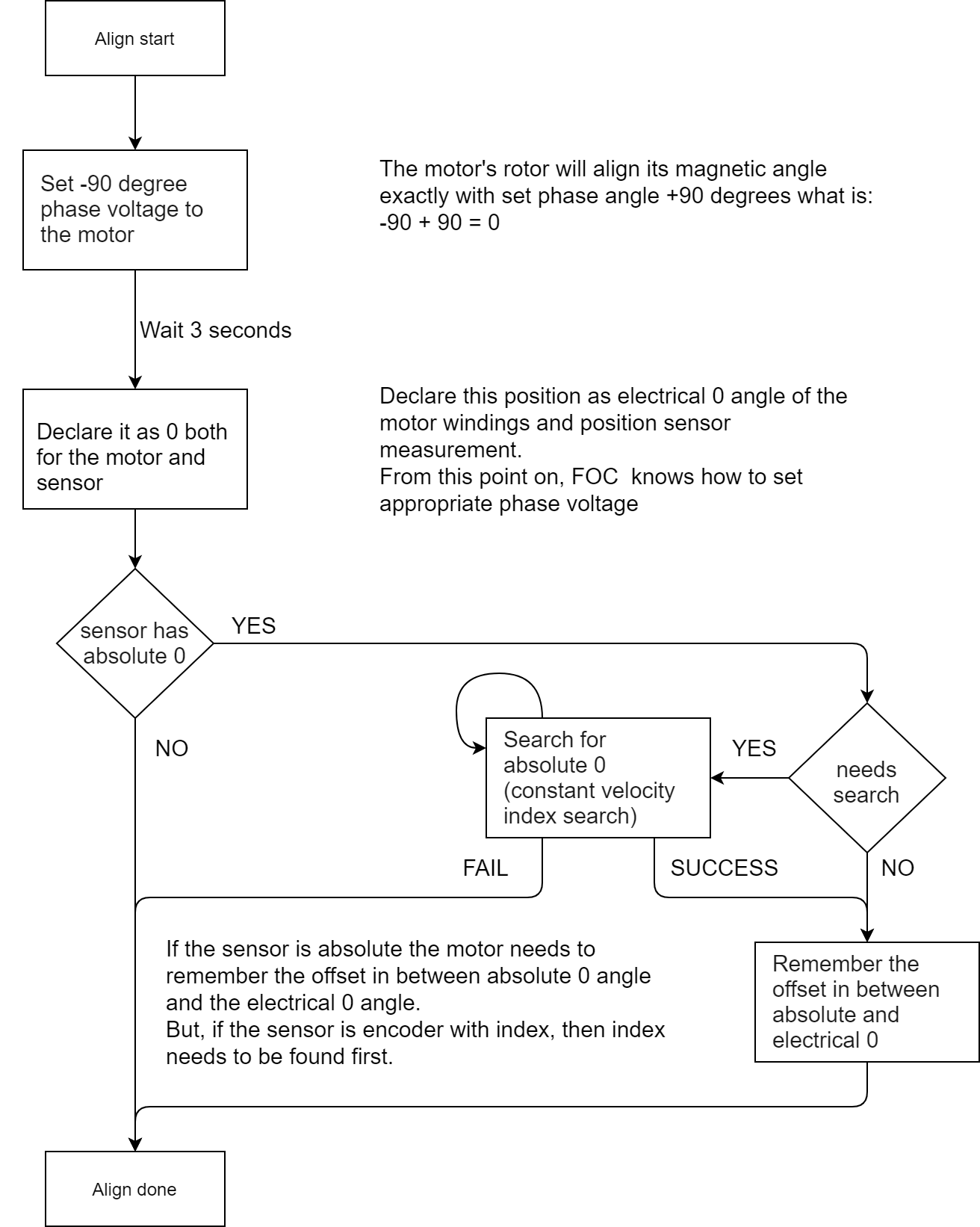
Sensor Alignment: alignSensor()
The sensor alignment procedure determines the sensor direction and finds the zero electrical angle:
// Encoder alignment to electrical 0 angle
int FOCMotor::alignSensor() {
  int exit_flag = 1;

  // Check if sensor needs zero search (e.g., encoder with index)
  if(sensor->needsSearch()) exit_flag = absoluteZeroSearch();
  if(!exit_flag) return exit_flag;

  float voltage_align = voltage_sensor_align;

  // If unknown natural direction
  if(sensor_direction == Direction::UNKNOWN) {

    // Move one electrical revolution forward
    for (int i = 0; i <= 500; i++) {
      float angle = _3PI_2 + _2PI * i / 500.0f;
      setPhaseVoltage(voltage_align, 0, angle);
      sensor->update();
      _delay(2);
    }
    sensor->update();
    float mid_angle = sensor->getAngle();

    // Move one electrical revolution backwards
    for (int i = 500; i >= 0; i--) {
      float angle = _3PI_2 + _2PI * i / 500.0f;
      setPhaseVoltage(voltage_align, 0, angle);
      sensor->update();
      _delay(2);
    }
    sensor->update();
    float end_angle = sensor->getAngle();
    _delay(200);

    // Determine sensor direction from movement
    float moved = fabs(mid_angle - end_angle);
    if (moved < MIN_ANGLE_DETECT_MOVEMENT) {
      return 0; // failed calibration - no movement detected
    } else if (mid_angle < end_angle) {
      sensor_direction = Direction::CCW;
    } else {
      sensor_direction = Direction::CW;
    }

    // Check pole pair number
    pp_check_result = !(fabs(moved * pole_pairs - _2PI) > 0.5f);
  }

  // Find zero electric angle if not set
  if(!_isset(zero_electric_angle)) {
    // Set angle -90° (270° = 3π/2) to align rotor
    setPhaseVoltage(voltage_align, 0, _3PI_2);
    _delay(700);

    // Read sensor and calculate zero offset
    sensor->update();
    zero_electric_angle = 0;
    zero_electric_angle = electricalAngle();
    _delay(20);

    // Stop motor
    setPhaseVoltage(0, 0, 0);
    _delay(200);
  }

  return exit_flag;
}
Current Sense Alignment: alignCurrentSense()
If current sensing is used, the library aligns the current sense phases with the driver:
// Calibrate the motor and current sense phases
int FOCMotor::alignCurrentSense() {
  int exit_flag = 1;

  // Align current sense and the driver
  exit_flag = current_sense->driverAlign(voltage_sensor_align, modulation_centered);
  if(!exit_flag) {
    // Error in current sense - phase not measured or bad connection
    exit_flag = 0;
  }

  return exit_flag > 0;
}
See here for a bit more theory behind the current sense alignment procedure
Key Alignment Steps
- Index Search: Find encoder index pulse if available
- Sensor Direction: Rotate motor forward and backward to detect CW or CCW orientation
- Pole Pair Check: Verify that the configured pole pairs match actual movement
- Zero Electric Angle: Align rotor to -90° electrical and record sensor offset
- Current Sense Alignment: Match current sense phase order with driver phases
See here for a bit more theory behind:
Position sensor alignment procedure Current sense alignment procedure
Skipping Alignment
-
Position sensor: You can skip alignment by setting
motor.sensor_directionandmotor.zero_electric_anglebefore callinginitFOC(). This is useful for absolute sensors (magnetic, hall) where the calibration values don’t change. -
Current sense: For current sensing, set
current_sense.skip_align = trueto skip phase alignment. This is useful if you have already verified that your current sense phases match the driver phases.
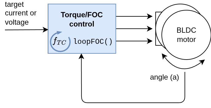
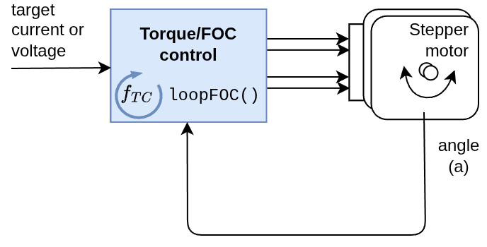
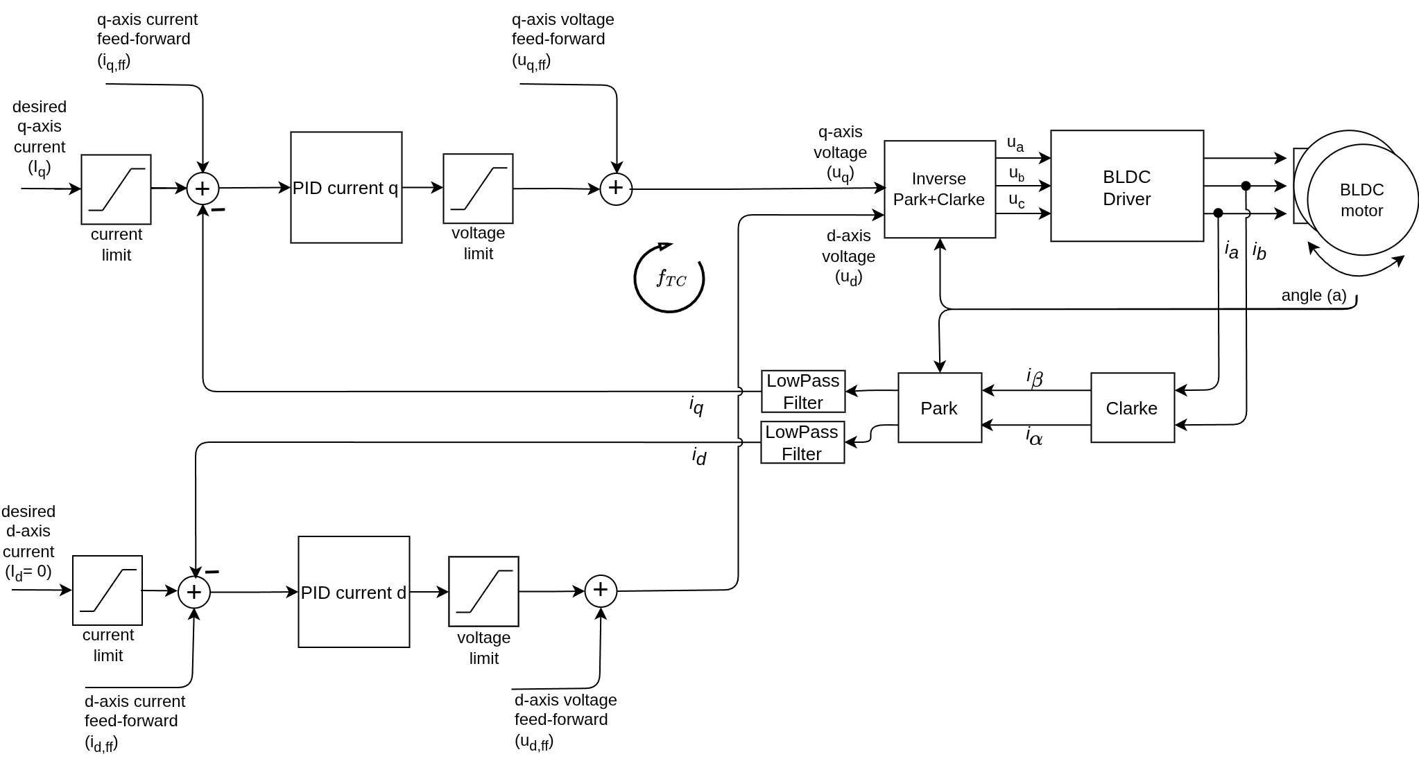
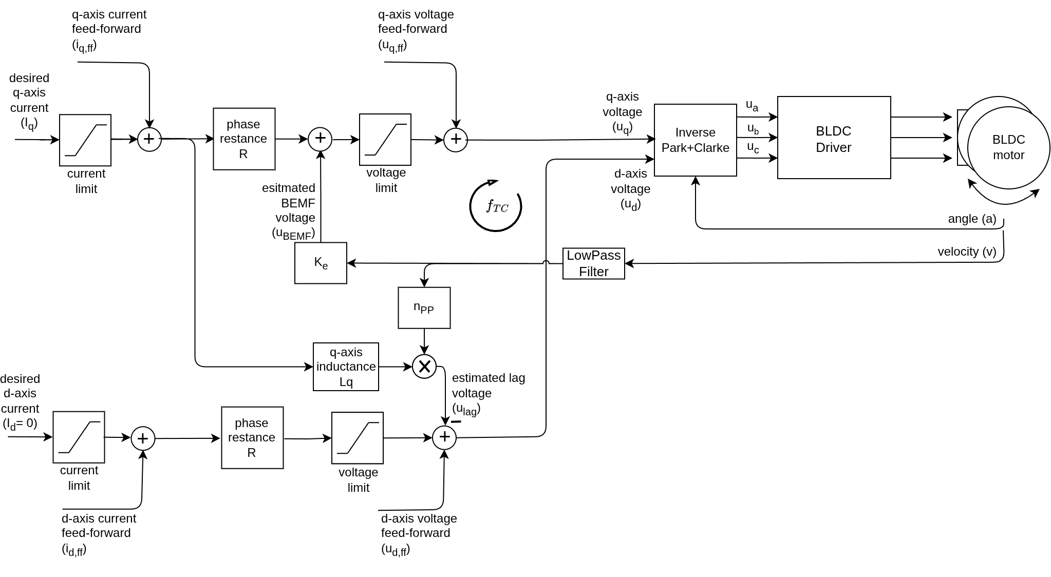
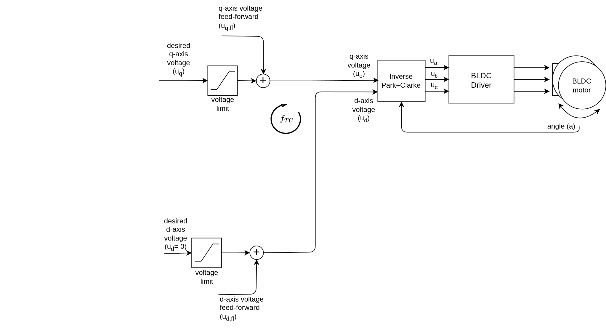
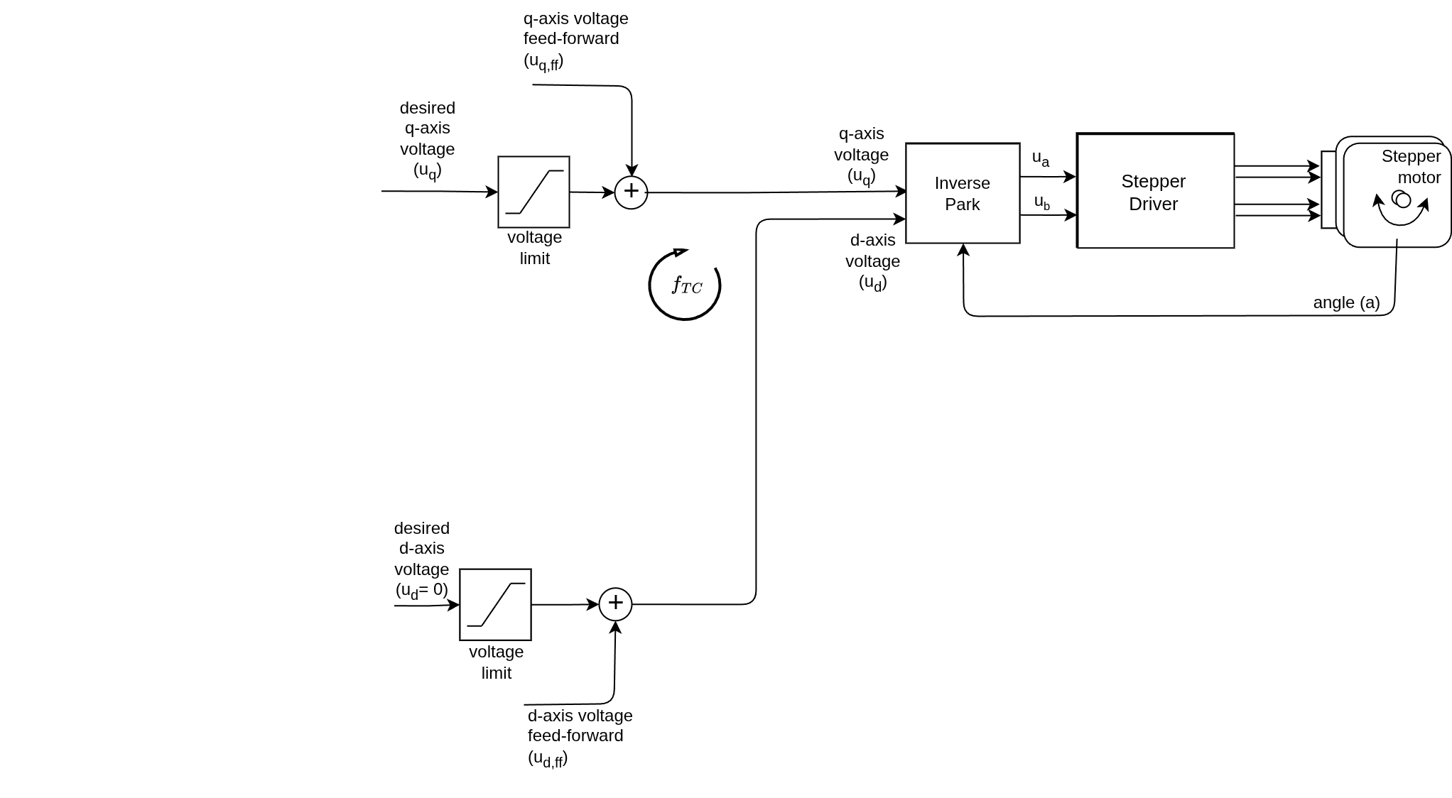
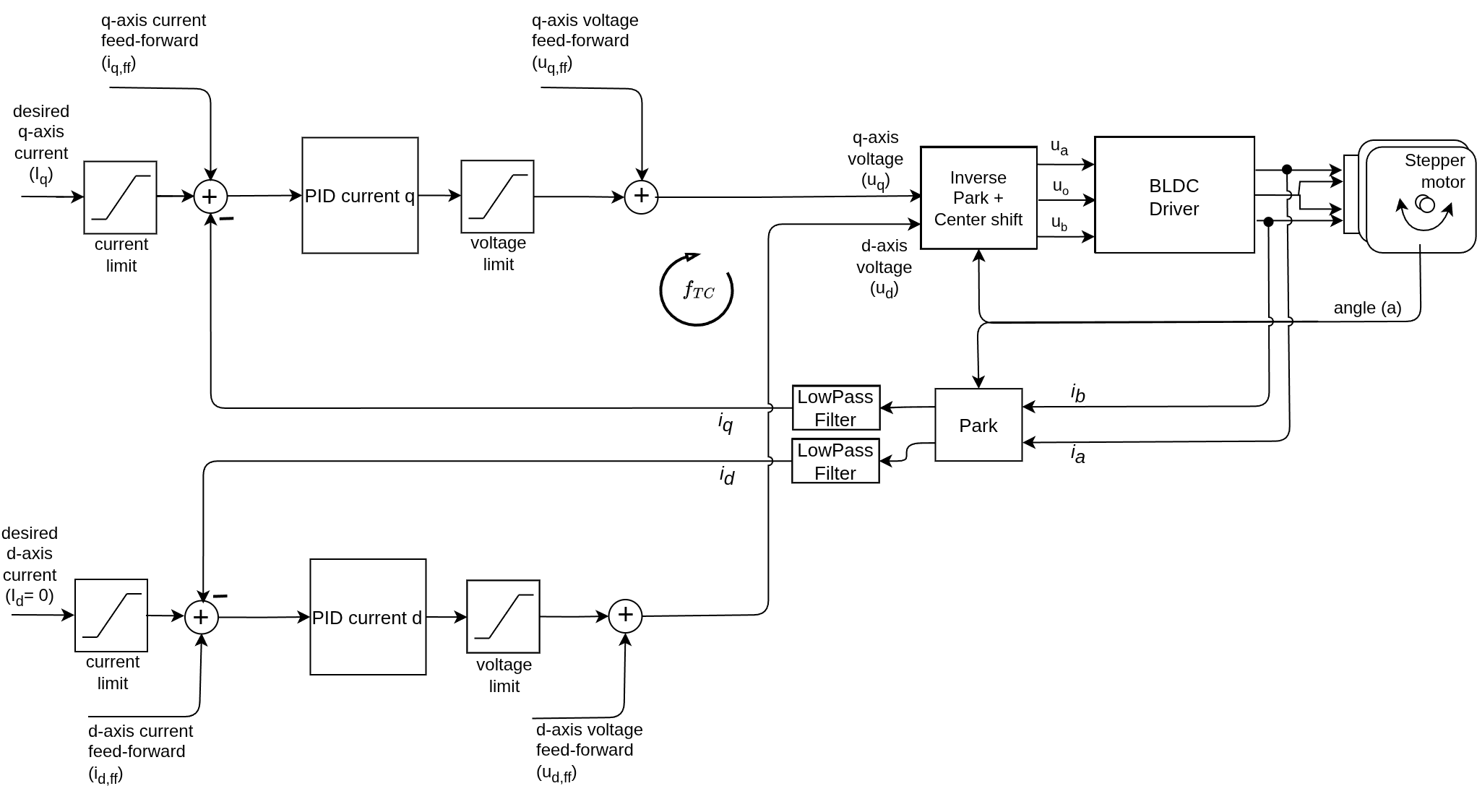
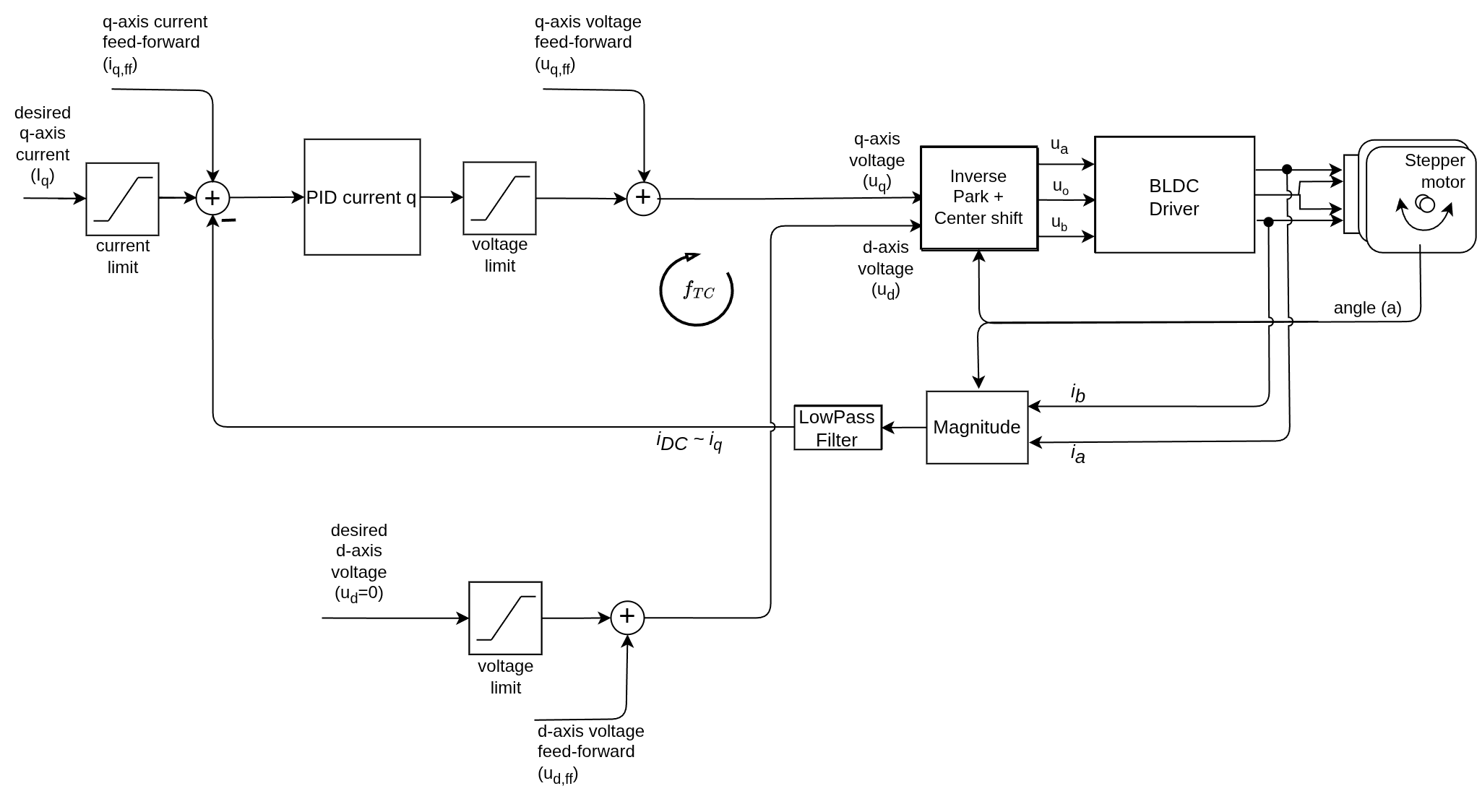
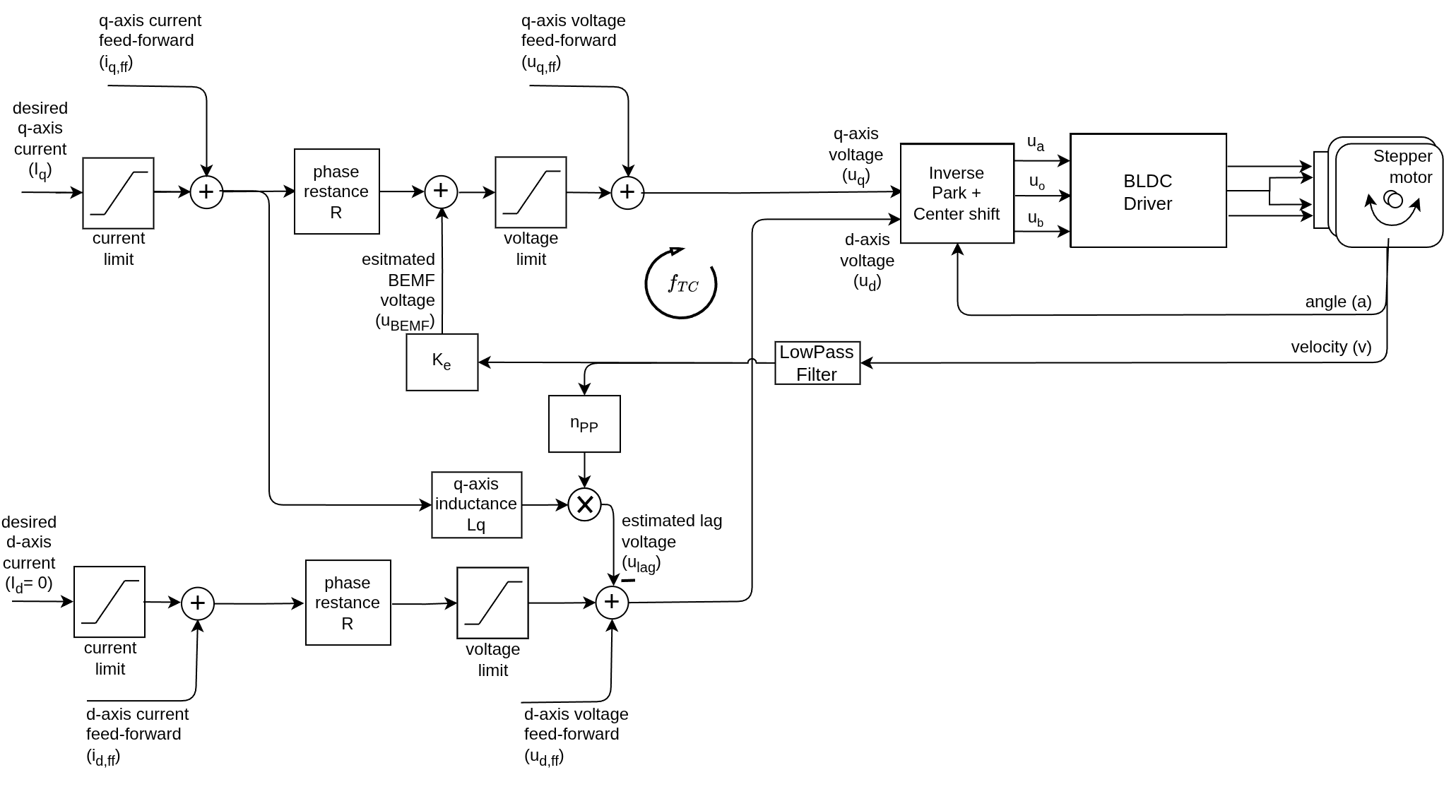
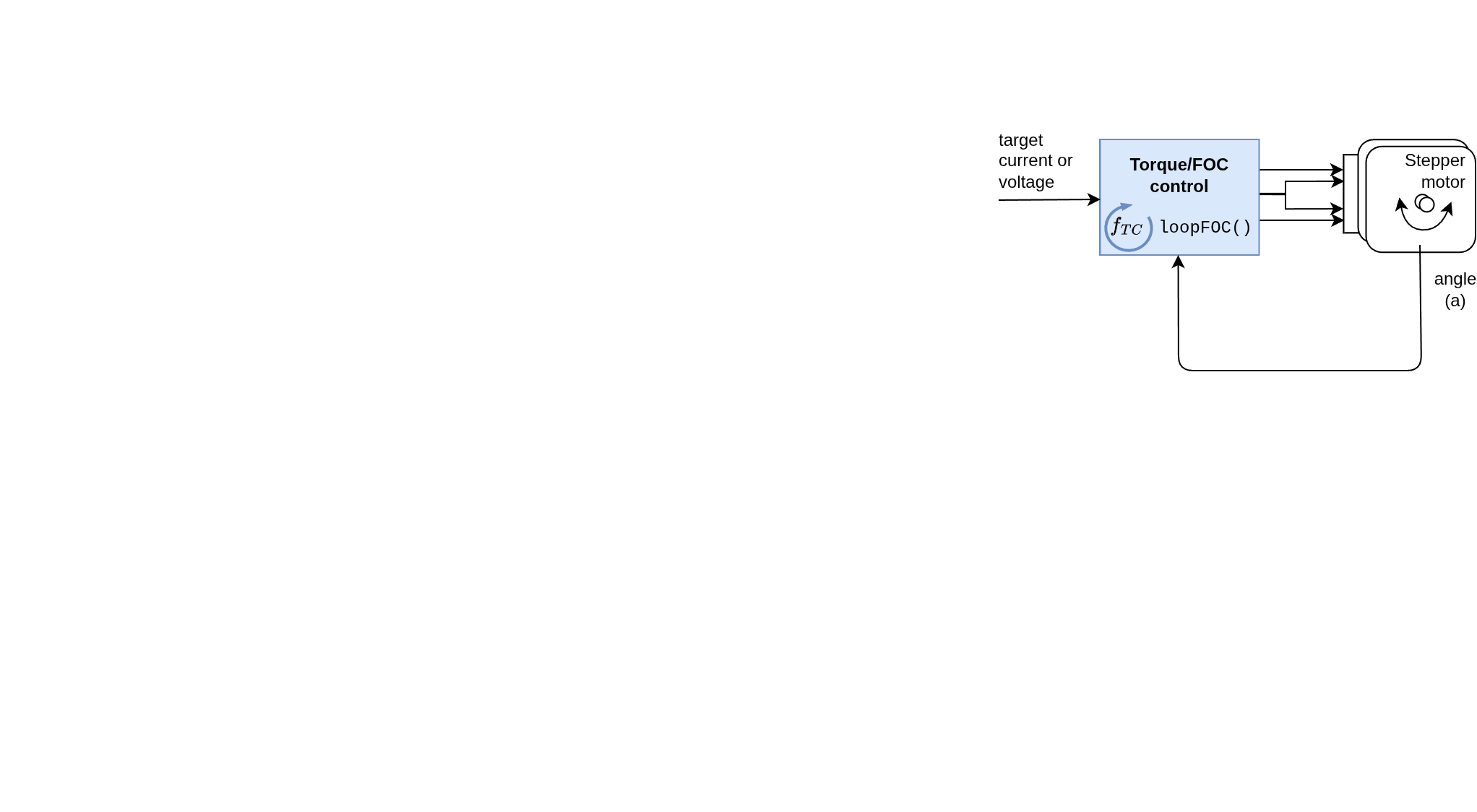
Real-Time Execution loopFOC()
The loopFOC() function is the real-time FOC routine that runs continuously. It reads the motor position, phase currents, calculates electrical angle, and sets appropriate voltages based on the selected torque control mode.
Choose the motor type:
BLDC motors Stepper motors Hybrid Stepper motors
Choose the voltage control type:
FOC current mode DC current mode Estimated current Voltage mode Conceptual


Implementation
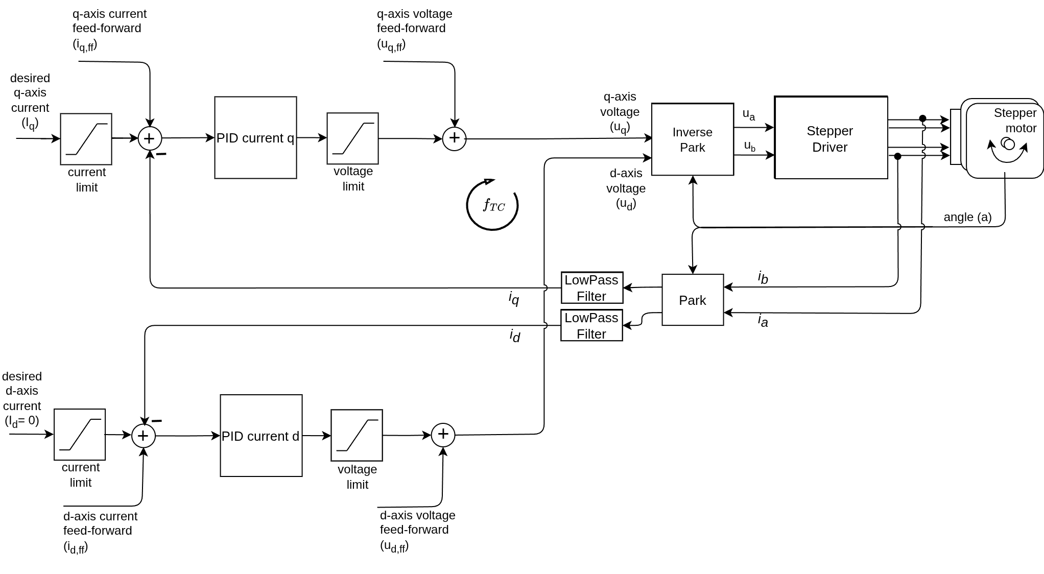
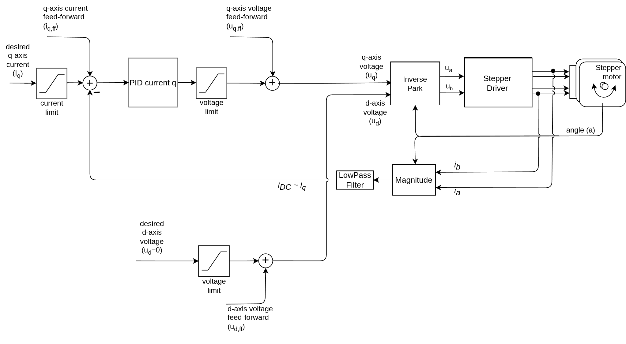
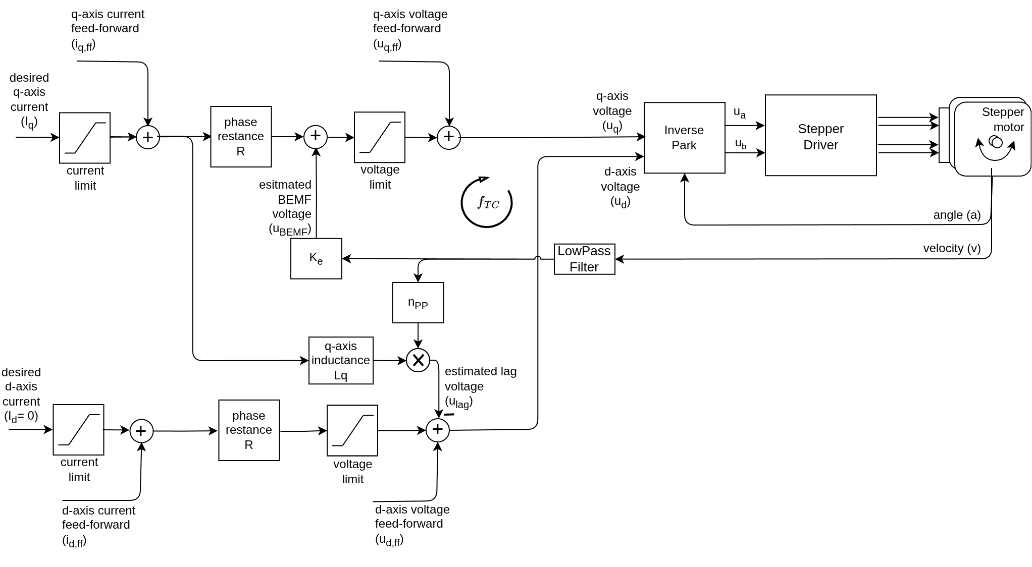
The loopFOC() function performs real-time torque control with multiple modes:
- Voltage control (directly setting voltage based on current setpoint, no current sensing)
- Estimated current control (using back-EMF estimation)
- DC current control (using overall current magnitude)
- FOC current control (using direct d and q current feedback)
All the control modes are interchangeable at runtime, and can be used with any motor type.
// Iterative function looping FOC algorithm, setting Uq on the Motor
// The faster it can be run the better: Arduino UNO ~1ms, Bluepill ~100us, ESP32 ~50us
void FOCMotor::loopFOC() {
  // Update loop time measurement
  updateLoopFOCTime();

  // Update sensor - done even in open-loop mode to track full rotations
  if (sensor) sensor->update();

  // If disabled or not ready, do nothing
  if(!enabled || motor_status != FOCMotorStatus::motor_ready) return;

  // Calculate electrical angle
  if(controller == MotionControlType::angle_openloop ||
     controller == MotionControlType::velocity_openloop) {
    // Open-loop: calculate from shaft_angle
    electrical_angle = _electricalAngle(shaft_angle, pole_pairs);
  } else {
    // Closed-loop: calculate from sensor (no numerical issues)
    electrical_angle = electricalAngle();
  }

  // Calculate voltages based on torque control mode
  switch (torque_controller) {
    case TorqueControlType::voltage:
      // Direct voltage control (no current sensing required)
      voltage.q = _constrain(current_sp, -voltage_limit, voltage_limit) + feed_forward_voltage.q;
      voltage.d = feed_forward_voltage.d;
      break;

    case TorqueControlType::estimated_current:
      if(!_isset(phase_resistance)) return;
      // Constrain current setpoint
      current_sp = _constrain(current_sp, -current_limit, current_limit) + feed_forward_current.q;
      // Calculate back-EMF voltage if KV_rating available: U_bemf = vel*(1/KV)
      if (_isset(KV_rating)) voltage_bemf = estimateBEMF(shaft_velocity);
      // Filter current value
      current.q = LPF_current_q(current_sp);
      // Calculate phase voltage: V = I*R + V_bemf
      voltage.q = current.q * phase_resistance + voltage_bemf;
      // Constrain and add feed-forward
      voltage.q = _constrain(voltage.q, -voltage_limit, voltage_limit) + feed_forward_voltage.q;
      // d voltage - lag compensation
      if(_isset(axis_inductance.q))
        voltage.d = _constrain(-current_sp * shaft_velocity * pole_pairs * axis_inductance.q,
                               -voltage_limit, voltage_limit) + feed_forward_voltage.d;
      else
        voltage.d = feed_forward_voltage.d;
      break;

    case TorqueControlType::dc_current:
      if(!current_sense) return;
      // Constrain current setpoint
      current_sp = _constrain(current_sp, -current_limit, current_limit) + feed_forward_current.q;
      // Read overall current magnitude
      current.q = current_sense->getDCCurrent(electrical_angle);
      // Filter current value
      current.q = LPF_current_q(current.q);
      // Calculate phase voltage using PID
      voltage.q = PID_current_q(current_sp - current.q) + feed_forward_voltage.q;
      // d voltage - lag compensation
      if(_isset(axis_inductance.q))
        voltage.d = _constrain(-current_sp * shaft_velocity * pole_pairs * axis_inductance.q,
                               -voltage_limit, voltage_limit) + feed_forward_voltage.d;
      else
        voltage.d = feed_forward_voltage.d;
      break;

    case TorqueControlType::foc_current:
      if(!current_sense) return;
      // Constrain current setpoint
      current_sp = _constrain(current_sp, -current_limit, current_limit) + feed_forward_current.q;
      // Read d and q currents
      current = current_sense->getFOCCurrents(electrical_angle);
      // Filter current values
      current.q = LPF_current_q(current.q);
      current.d = LPF_current_d(current.d);
      // Calculate phase voltages using PID
      voltage.q = PID_current_q(current_sp - current.q);
      voltage.d = PID_current_d(feed_forward_current.d - current.d);
      // d voltage - lag compensation (decoupling)
      if(_isset(axis_inductance.q))
        voltage.d = _constrain(voltage.d - current_sp * shaft_velocity * pole_pairs * axis_inductance.q,
                               -voltage_limit, voltage_limit);
      // q voltage - cross coupling compensation
      if(_isset(axis_inductance.d))
        voltage.q = _constrain(voltage.q + current.d * shaft_velocity * pole_pairs * axis_inductance.d,
                               -voltage_limit, voltage_limit);
      // Add feed-forward voltages
      voltage.q += feed_forward_voltage.q;
      voltage.d += feed_forward_voltage.d;
      break;

    default:
      // No torque control selected
      return;
  }

  // Set phase voltages - FOC heart function!
  setPhaseVoltage(voltage.q, voltage.d, electrical_angle);
}
Go to Torque/FOC control API docs Go to Torque control implementation docs
Related Documentation
Motion Control Implementation Torque Control Implementation PID Implementation Low-Pass Filter Implementation