On this page
Connecting the hardware to SimpleFOCMini v1.1
Connecting the SimpleFOCMini v1.1 to the microcontroller, BLDC motor and power-supply is very straight forward.
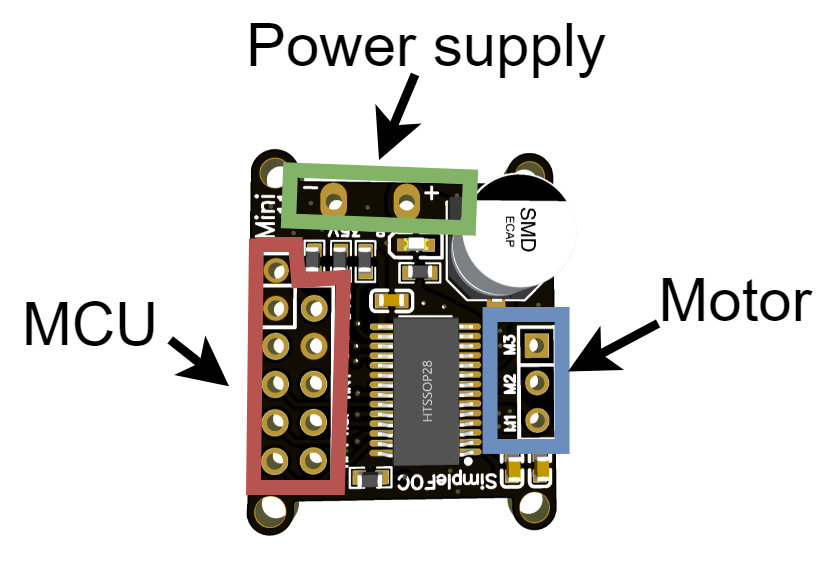
Microcontroller
- SimpleFOCMini v1.1 is designed as a standalone BLDC driver, which will basically work with any microcontroller.
- This board has 11 pins exposed for the connection to the microcontroller
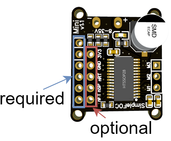
There are 4 pins that are required to be connected: IN1, IN2, IN3 and EN. Additionally, the GND pin is required to be connected to the microcontroller’s GND pin. SimpleFOCMini v1.1 has two GND pins exposed in first line of the header to make it easier to connect to the microcontroller. You can choose the one which is more convenient to your application.
| Pin Name | Description |
|---|---|
| GND | Ground (common ground) |
| GND | Ground (common ground) |
| EN | Driver Enable |
| IN3 | PWM input phase 3 |
| IN2 | PWM input phase 2 |
| IN1 | PWM input phase 1 |
BEWARE: pin order
Version v1.1 of the SimpleFOCMini has the order of the IN1,IN2,IN3 and EN changed with respect to the v1.0.
These pins need to be connected whenever using the SimpleFOCMini. The 3 pwm pins and the enable pin are used to control the DRV8313 driver and in terms of the SimpleFOClibrary they correspond to the entries of the BLDCDriver3PWM class. The common ground pin is very important as well in order to make sure that all the PWM and Enable pins are read properly by the driver chip. Once you decide which pins you will be using for INx and EN pins you will be able to provide them to the BLDCDriver3PWM class in your Arduino sketch.
BLDCDriver3PWM driver = BLDCDriver3PWM(IN1, IN2, IN3, EN);
In addition to these pins there are 5 pins that are optional.
| Pin Name | Description |
|---|---|
| 3.3V | 3.3V output - NOT INPUT |
| GND | Ground |
| nRT | Reset (active LOW) |
| nSP | Sleep (active LOW) |
| nFT | Fault output (active LOW) |
SimpleFOCMini is based on the DRV8313 driver which has integrated 3.3V regulator which might be useful in some applications to power a sensor or similar. The 3.3v pin of the SimpleFOCMini can therefore be used as a 3.3v source pin with the maximum current output of 10mA. Both GND pins exposed in the SimpleFOCMini’s header are connected to the same ground, so you can choose the one which is more convenient to your application.
BEWARE: 3.3V LDO Power limitations
DRV8313 comes with the 3.3V voltage regulator and it is connected to the SimpleFOCMini's 3.3V pin. However it has a limitation of 10mA, which is in general not enough to power a microcontroller. But it might be enough to power a LED light or some position sensors.
Pin nFT (fault) is an active LOW output of the SimpleFOCMini which can be read to verify if the DRV8313 driver is working properly. If this pin is in LOW it means the DRV8313 is its fault state and it cannot drive the motor. Then the pin nRT (reset), which is also active LOW, can be used to reset the DRV8313 driver to reinitialise its internal state and exit the fault state, this cannot be done by simply toggling the enable pin. Finally the pin nSP (sleep) is an active LOW pin that puts the DRV8313 in the low-power sleep mode, consuming the current of under 1uA.
BLDC motor
- Motor phases
a,bandcare connected directly the motor terminal connectorM1,M2andM3
BEWARE: Power limitations
SimpleFOCMini is designed for gimbal motors with internal resistance higher than R>10Ohm. The absolute maximal current of this board is 5A. Please make sure when using this board in your projects that the BLDC motor used does comply with these limits.
If you still want to use this driver with the BLDC motors with very low resistance R < 1Ohm make sure to limit the voltage set to the board.
For a bit more information about the choice of motors visit BLDC motor docs
Power supply
- Power supply cables are connected directly to the terminal pins
+and- - Required power supply voltage is from 8V to 35V.
Examples of connection schematics
SimpleFOCMini can be connected to any microcontroller (MCU) pin combination that can ensure that the mini’s GND pin is connected to the MCU’s GND pin, MCU’s 3 pwm capable pins are connected to the IN1,IN2 and IN3 pins, and one MCU’s digital pin is connected to the EN pin.
Nucleo board
An example connection of the SimpleFOCMini and Nucleo board is shown on the image below.
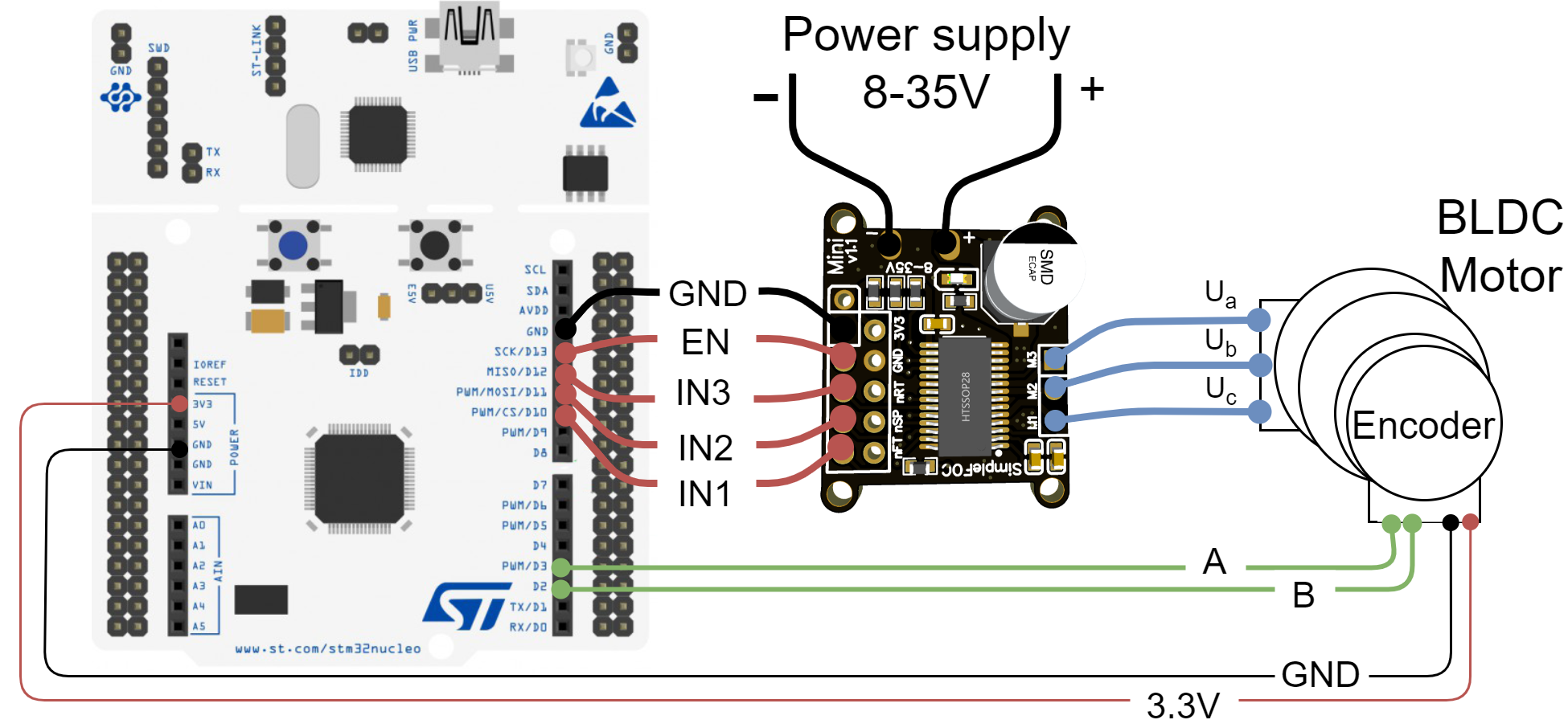
SimpleFOCMini can be directly plugged into the Arduino headers of teh Nucleo board from the pin 10 to the GND pin and in that way reduce the amount of wires necessary. For more information on this example connection see this library example.
| Mini Pin | IN1 | IN2 | IN3 | EN | GND |
| Nucleo Pin | 10 | 11 | 12 | 13 | GND |
BLDCDriver3PWM driver = BLDCDriver3PWM(10, 11, 12, 13);
Arduino UNO board
An example connection of the SimpleFOCMini and Arduino UNO is shown on the image below. 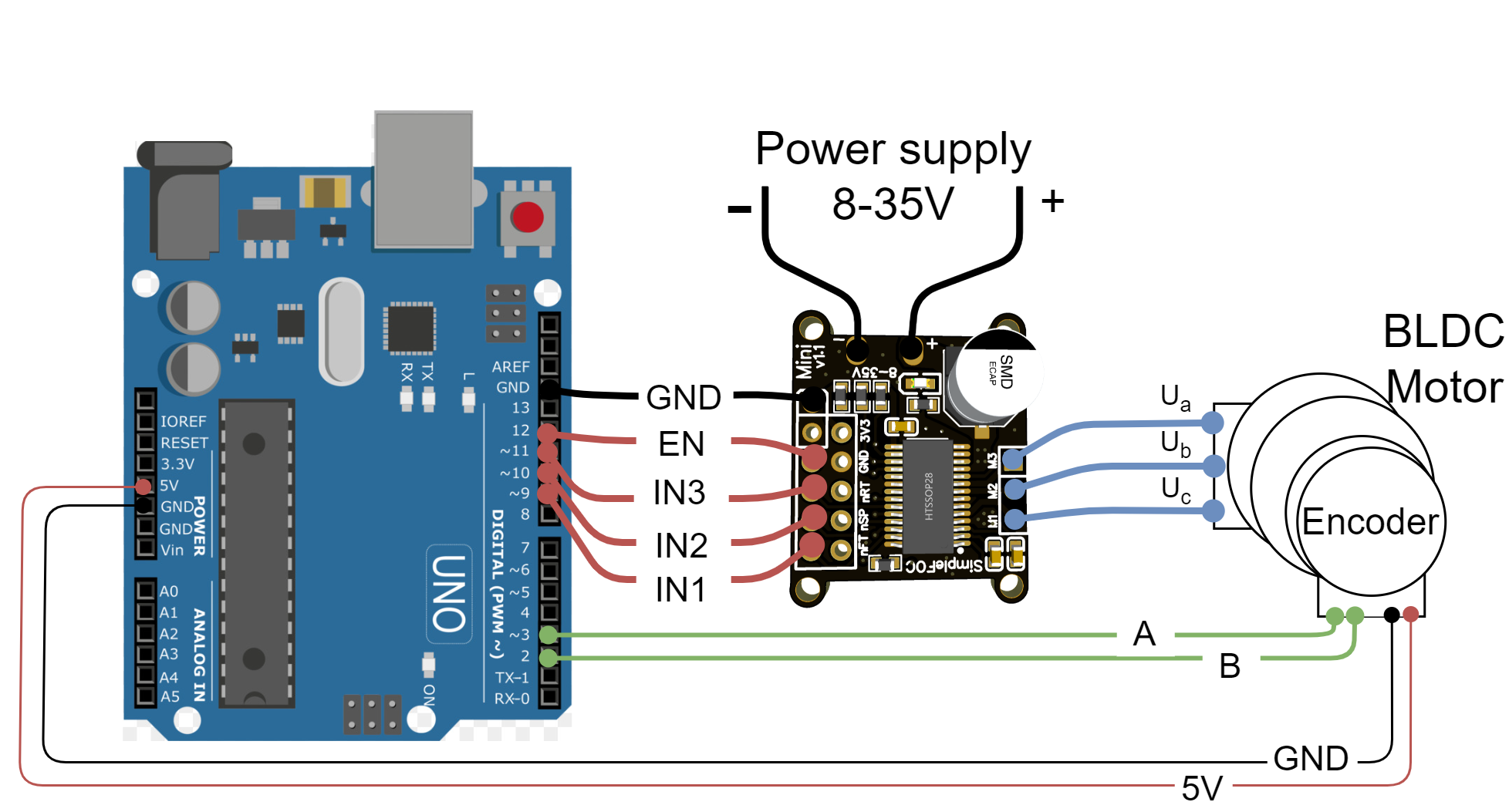
SimpleFOCMini can be directly plugged into the Arduino headers of the UNO board from the pin 9 to the 12 pin and the GND pin connected to the Arduino’s GND pin (skipping the pin 13). This stacking capability allows to reduce reduce the amount of wires necessary. For more information on this example connection see this library example.
| Mini Pin | IN1 | IN2 | IN3 | EN | GND |
| UNO Pin | 9 | 10 | 11 | 12 | GND |
BLDCDriver3PWM driver = BLDCDriver3PWM(9, 10, 11, 12);
Another example of connecting the Arduino UNO with SimpleFOCMini is shown below 
| Mini Pin | IN1 | IN2 | IN3 | EN | GND |
| UNO Pin | 5 | 6 | 9 | 12 | GND |
BLDCDriver3PWM driver = BLDCDriver3PWM(5, 6, 9, 12);
Bluepill board
An example connection of the SimpleFOCMini and stm32 Bluepill is shown on the image below. The mini can be stacked on the bluepill headers directly from pin PB6 to PB9, skipping the 5V pin and the GND pin connected to the Bluepill’s GND pin. 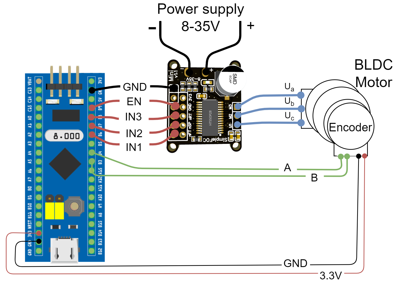
| Mini Pin | IN1 | IN2 | IN3 | EN | GND |
| Bluepill Pin | PB6 | PB7 | PB8 | PB9 | GND |
BLDCDriver3PWM driver = BLDCDriver3PWM(PB6, PB7, PB8, PB9);
Qtpy or Seed Xiao boards
The simplest way of connecting the SimpleFOCMini to the Qtpy or Seed Xiao boards is as shown in the image below. The mini can be stacked on the Qtpy headers directly from pin 8 to 10, using 3.3V pin for EN and the GND pin connected to the Qtpy’s GND pin.
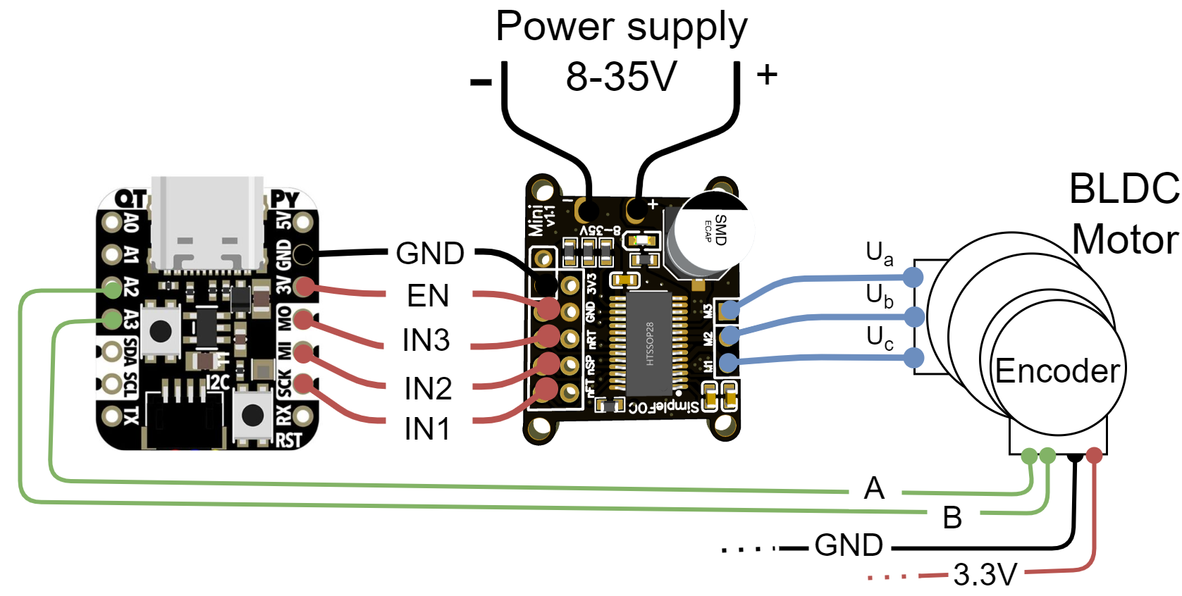
| Mini Pin | IN1 | IN2 | IN3 | EN | GND |
| Qtpy Pin | 8 | 9 | 10 | 3.3V | GND |
BLDCDriver3PWM driver = BLDCDriver3PWM(8, 9, 10);
Note: Enable pin always high
With this connection setup there is no possibility to disable the driver using the `EN` pin. The driver will be always enabled.