On this page
BLDC driver 6PWM - BLDCDriver6PWM
This is the class which provides an abstraction layer of most of the common 6 PWM BLDC drivers out there. Basically any BLDC driver board that can be run using 6 PWM signals can be represented with this class. Examples:
- DRV830x ( can be run in 3 PWM or 6 PWM mode )
- ST B-G431B
- X-NUCLEO-IHM08M1
- ODrive 3.6
- etc.
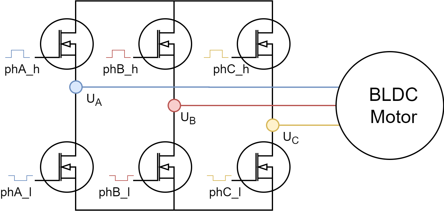
6 PWM control mode gives much more freedom for BLDC motor control than 3PWM control since each of the 6 half-bride mosfets can be controlled separately.
Step 1. Hardware setup
To create the interface to the BLDC driver you need to specify the 6 PWM pin numbers for each motor phase and optionally enable pin.
//  BLDCDriver6PWM( int phA_h, int phA_l, int phB_h, int phB_l, int phC_h, int phC_l, int en)
//  - phA_h, phA_l - A phase pwm pin high/low pair
//  - phB_h, phB_l - B phase pwm pin high/low pair
//  - phB_h, phC_l - C phase pwm pin high/low pair
//  - enable pin    - (optional input)
BLDCDriver6PWM driver = BLDCDriver6PWM(5,6, 9,10, 3,11, 8);
⚠️ 6 PWM configuration is very hardware specific and please make sure to respect certain guidelines in order for it to work properly!
📢 Here is a quick guide to choosing appropriate PWM pins for different MCU architectures see in docs.
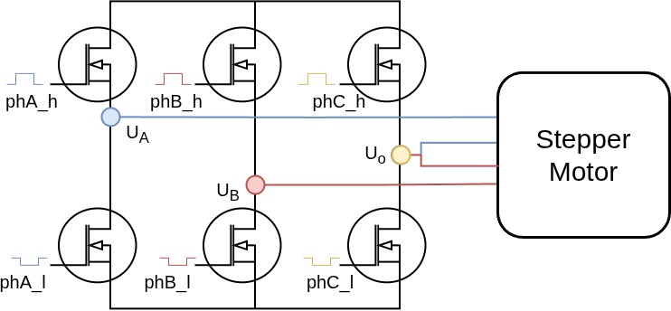
⚠️ Note: When using the 6PWM BLDC driver with a stepper motor, ensure that the common phase `Uo` is connected to the driver's C phase pin.
Even if the common phase
Uois physically connected to some other driver output (AorB), please provide it as theCphase pin in the driver constructor. This is important for the correct operation of the stepper motor.Consider an example of the driver connected to the MCU pins as follows:
#define PIN_A_H 9
#define PIN_A_L 10
#define PIN_B_H 11
#define PIN_B_L 12
#define PIN_C_H 13
#define PIN_C_L 14
#define ENABLE 8
If the common phase
Uois connected to the driver pinA, you should still provide it as theCphase pin in the driver constructor:// common phase `Uo` connected to driver pin `A` so it is provided as the `C` phase pin BLDCDriver6PWM driver = BLDCDriver6PWM(PIN_C_H, PIN_C_L, PIN_B_H, PIN_B_L, PIN_A_H, PIN_A_L, ENABLE);If the common phase
Uois connected to the driver pinB, you should provide it as theCphase pin in the driver constructor:// common phase `Uo` connected to driver pin `B` so it is provided as the `C` phase pin BLDCDriver6PWM driver = BLDCDriver6PWM(PIN_A_H, PIN_A_L, PIN_C_H, PIN_C_L, PIN_B_H, PIN_B_L, ENABLE);Or if the common phase
Uois connected to the driver pinC, you should provide it as theCphase pin in the driver constructor:// common phase `Uo` connected to driver pin `C` so it is provided as the `C` phase pin BLDCDriver6PWM driver = BLDCDriver6PWM(PIN_A_H, PIN_A_L, PIN_B_H, PIN_B_L, PIN_C_H, PIN_C_L, ENABLE);
Arduino UNO support
Arduino UNO and all the atmega328 based boards have only 6 PWM pins and in order to use the BLDCDrievr6PWM we need to use all of them. Those are 3,5,6,9,10 and 11. Furthermore in order for the algorithm to work well we need to use the PWM pins that belong to the same timer for each high/low side pair of each phase. So Atmega328 pins belonging to the timers are:
TIM0 | TIM1 | TIM2 |
|---|---|---|
5,6 | 9,10 | 3,11 |
Therefore it is important that phA_h and phA_l belong to one timer, phB_h and phB_l to second timer and phC_h and phC_l to the last timer. If we decide that phase A belongs to the timer TIM0 we can set phA_h either to pin 5 or pin 6.
STM32 support
Stm32 boards have two possible 6 PWM modes:
- Hardware 6 PWM mode
- Software 6 PWM mode
Hardware 6 PWM mode
In hardware 6 PWM mode the user uses only one timer, usually Timer 1 for all the 6 PWM channels. Stm32 boards usually have at least one timer which has automatic complementary channels which avoids the need for a complicated channel inverting configuration. SimpleFOClibrary automatically enables this control mode if you provide the pins that support this interface to the constructor of the BLDCDriver6PWM class. For example, both STM32 Bluepill and STM32 Nucleo boards have this interface supported by pins:
T1C1 | T1C2 | T1C3 | T1C1N | T1C2N | T1C3N |
|---|---|---|---|---|---|
PA8 | PA9 | PA10 | PB13 | PB14 | PB15 |
Where T1Cx are the Timer 1 channels and T1CxN are their complementary channels (inverted channels). Each pair of T1Cx and T1CxN is used for one pair of the high/low PWM pins. The library will configure the necessary timers and registers if you provide these pins to the constrictor of the BLDCDriver6PWM class. For example:
//  BLDCDriver6PWM( int phA_h, int phA_l, int phB_h, int phB_l, int phC_h, int phC_l, int en)
BLDCDriver6PWM driver = BLDCDriver6PWM(PA8, PB13, PA9, PB14, PA10, PB15);
Software 6 PWM mode
If it is not possible to use the hardware 6 PWM mode with your board SimpleFOClibrary enables you to use any two channels of any of the timers as your high/low side PWM pair. Basically, the library will automatically configure the complementary channels on the provided low side pins. The only requirement for this code to work properly is exatcly the same as for the Arudino UNO, each phase high/low PWM pair needs to belong to the same timer. For example, if we take STM32 Nucleo F401RE board we can take for example:
//  BLDCDriver6PWM( int phA_h, int phA_l, int phB_h, int phB_l, int phC_h, int phC_l, int en)
BLDCDriver6PWM driver = BLDCDriver6PWM(7, 2, 6, 3, 5, 4);
Where
T1C1 | T1C3 | T2C3 | T2C2 | T3C1 | T3C2 |
|---|---|---|---|---|---|
7 | 2 | 6 | 3 | 5 | 4 |
On Bluepill we could use:
//  BLDCDriver6PWM( int phA_h, int phA_l, int phB_h, int phB_l, int phC_h, int phC_l, int en)
BLDCDriver6PWM driver = BLDCDriver6PWM(PA8, PA9, PB6, PB7, PB8, PB9);
Where
T1C1 | T1C2 | T4C1 | T4C2 | T4C3 | T4C4 |
|---|---|---|---|---|---|
PA8 | PA9 | PB6 | PB7 | PB8 | PB9 |
ESP32 support
ESP32 boards support MCPWM interface that is intended for this kind of applications. Each ESP32 board has two of the MCPWM channels and can support two 6 PWM drivers. There is no pin specific requirements for the ESP32, each pin can be used in PWM mode. But please make sure not to use the pins that have predefined states on boot because this could result malfunction. You can find this information online easily, here is a YouTube video with more details.
Low-side current sensing considerations
As ADC conversion has to be synchronised with the PWM generated on ALL the phases, it is important that all the PWM generated for all the phases have aligned PWM. Since the microcontrollers usually have more than one timer for PWM generation on its pins, different architectures of microcontrollers have different degrees of alinement in between the PWM generated from different timers.
RULE OF THUMB: PWM timer pins
In order to maximise your chances for the low-side current sensing to work well we suggest to make sure that the PWM pins chosen for your driver all belong to the same timer. Finding out which pins belong to different timers might require some time to be spent in the MCU datasheet 😄 To try to save you some time, we have created a quick guide to choosing appropriate PWM pins for different MCU architectures see in docs. You can also always ask the community for help - community link!
Step 2.1 PWM Configuration
// pwm frequency to be used [Hz]
// for atmega328 either 4k or 32kHz
// esp32/stm32/teensy configurable
driver.pwm_frequency = 20000;
Here is a list of different microcontrollers and their PWM frequency and resolution used with the Arduino SimpleFOClibrary.
| MCU | default frequency | MAX frequency | PWM resolution | Center-aligned | Configurable freq |
|---|---|---|---|---|---|
| Arduino UNO(Atmega328) | 32 kHz | 32 kHz | 8bit | yes | yes (either 4kHz or 32kHz) |
| STM32 | 25kHz | 50kHz | 14bit | yes | yes |
| ESP32 | 30kHz | 50kHz | 10bit | yes | yes |
| Teensy | 25kHz | 50kHz | 8bit | yes | yes |
All of these settings are defined in the drivers/hardware_specific/x_mcu.cpp/h of the library source.
Low-side current sensing considerations
As the ADC conversion takes some time to finish and as this conversion has to happen only during the specific time window ( when all the phases are grounded - low-side mosfets are ON ) it is important to use an appropriate PWM frequency. PWM frequency will determine how long each period of the PWM is and in term how much time the low-side switches are ON. Higher PWM frequency will leave less time for the ADC to read the current values.
On the other hand, having higher PWM frequency will produce smoother operation, so there is definitely a tradeoff here.
RULE OF THUMB: PWM frequency
The rule of thumb is to stay arround 20kHz.driver.pwm_frequency = 20000;
Step 2.2 Dead zone (dead time)
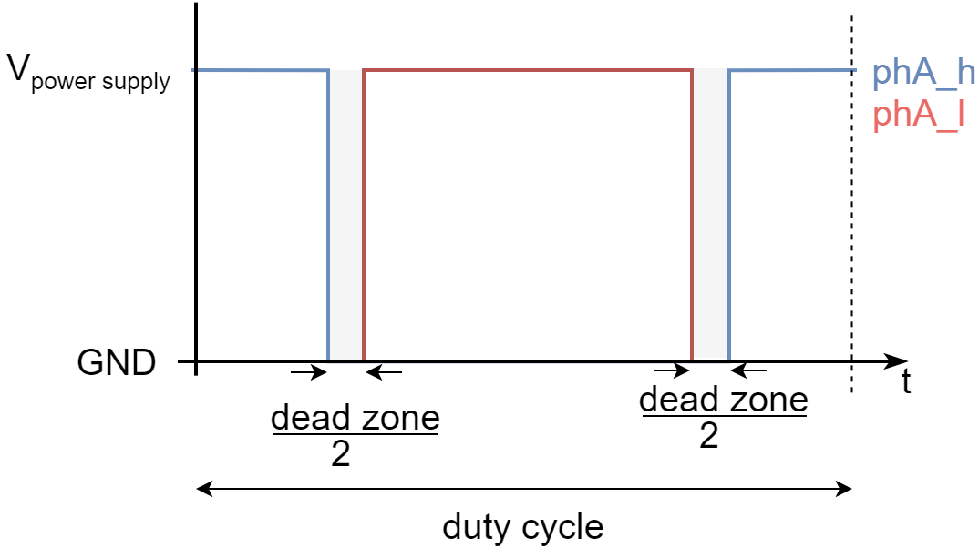
// dead_zone [0,1] - default 0.02 - 2%
driver.dead_zone = 0.05;
The dead zone parameter is defined as the amount of the duty cycle that is reserved in between changing the active mosfet. Each time the high/low side is deacitvated and low/high side is activated half of the dead_zone is injected. This parameter is equivalent to the dead time, dead_time can be calculated as:
dead_time = 1/pwm_frequency*dead_zone
Step 2.2 Voltages
Driver class is the one that handles setting the PWM duty cycles to the driver output pins and it is needs to know the DC power supply voltage it is plugged to. Additionally driver class enables the user to set the absolute DC voltage limit the driver will be set to the output pins.
// power supply voltage [V]
driver.voltage_power_supply = 12;
// Max DC voltage allowed - default voltage_power_supply
driver.voltage_limit = 12;
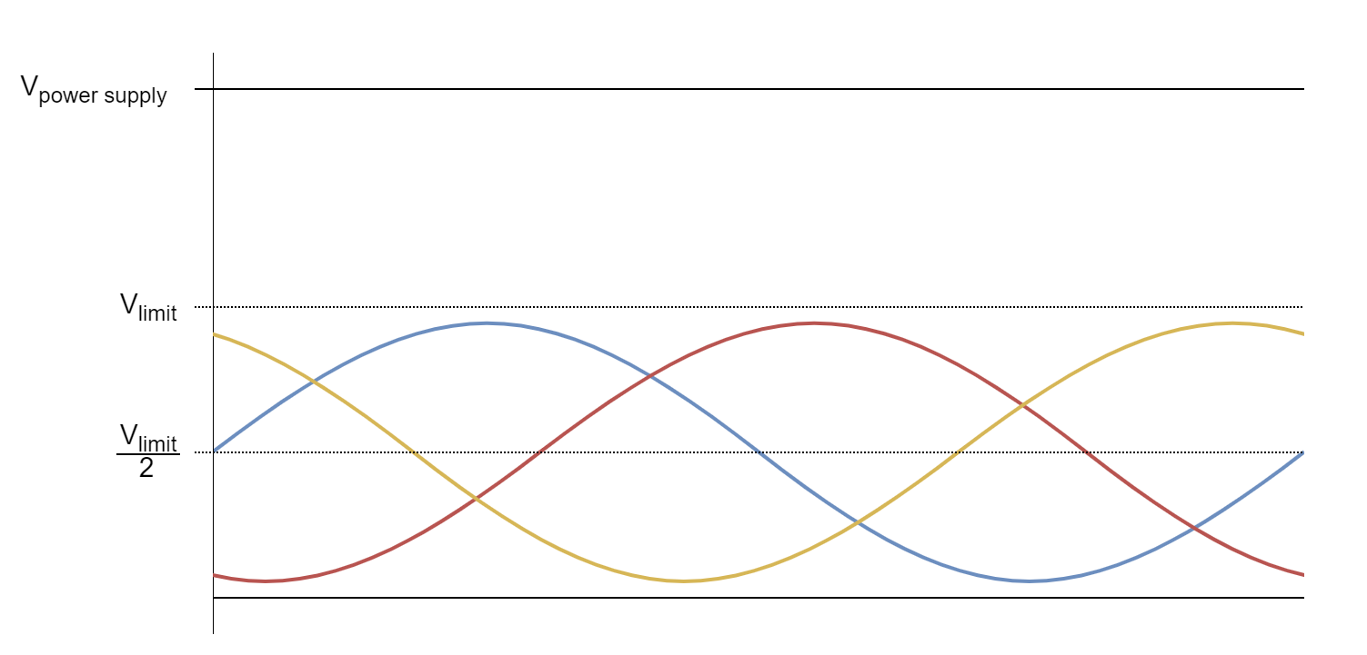
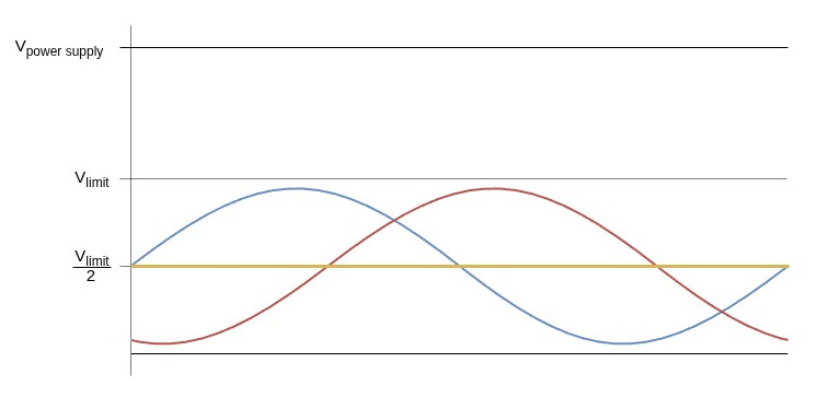
This parameter is used by the BLDCMotor class as well. As shown on the figure above the once the voltage limit driver.voltage_limit is set, it will be communicated to the FOC algorithm in BLDCMotor class and the phase voltages will be centered around the driver.voltage_limit/2.
Therefore this parameter is very important if there is concern of too high currents generated by the motor. In those cases this parameter can be used as a security feature.
Step 2.3 Initialisation
Once when all the necessary configuration parameters are set the driver function init() is called. This function uses the configuration parameters and configures all the necessary hardware and software for driver code execution.
// driver init
driver.init();
This function is responsible for:
- determining and configuring the hardware timer for PWM generation
- verifying that all provided pins can be used to generate PWM
- configuring the PWM channels
If for some reason the driver configuration fails this function will return 0 if everything went well the function will return 1. So we suggest you to check if the init function was executed successfully before continuing
Serial.print("Driver init ");
// init driver
if (driver.init())  Serial.println("success!");
else{
  Serial.println("failed!");
  return;
}
Enable debugging output
If you wish to see a more verbose debugging output of the driver configuration during the driver.init() and see more details about the driver configuration and possible errors, you can use the SimpleFOCDebug class. In order to enable the verbose debugging mode make sure to enable debugging before the driver.init() call, preferably at the top of the setup() function.
Serial.begin(115200); // to output the debug information to the serial
SimpleFOCDebug::enable(&Serial);
See more in the SimpleFOCDebug documentation.
📢 We strongly advise to use the debugging mode when starting with the SimpleFOClibrary. It provides much more information than the standard monitoring output and can help troubleshooting potentially problems, even MCU architecture specific ones.
Step 3. Using BLDCDriver6PWM in real-time
BLDC driver class was developed to be used with the SimpleFOClibrary and to provide the abstraction layer for FOC algorithm implemented in the BLDCMotor class. But the BLDCDriver3PWM class can used as a standalone class as well and once can choose to implement any other type of control algorithm using the BLDC driver.
FOC algorithm support
In the context of the FOC control all the driver usage is done internally by the motion control algorithm and all that is needed to enable is is just link the driver to the BLDCMotor class.
// linking the driver to the motor
motor.linkDriver(&driver)
Standalone driver
If you wish to use the BLDC driver as a standalone device and implement your-own logic around it this can be easily done. Here is an example code of a very simple standalone application.
// BLDC driver standalone example
#include <SimpleFOC.h>

// BLDC driver instance
BLDCDriver6PWM driver = BLDCDriver6PWM(5, 6, 9,10, 3, 11, 8);

void setup() {

  // pwm frequency to be used [Hz]
  driver.pwm_frequency = 20000;
  // power supply voltage [V]
  driver.voltage_power_supply = 12;
  // Max DC voltage allowed - default voltage_power_supply
  driver.voltage_limit = 12;
  // daad_zone [0,1] - default 0.02 - 2%
  driver.dead_zone = 0.05;

  // driver init
  driver.init();

  // enable driver
  driver.enable();

  _delay(1000);
}

void loop() {
    // setting pwm
    // phase A: 3V, phase B: 6V, phase C: 5V
    driver.setPwm(3,6,5);
}