On this page
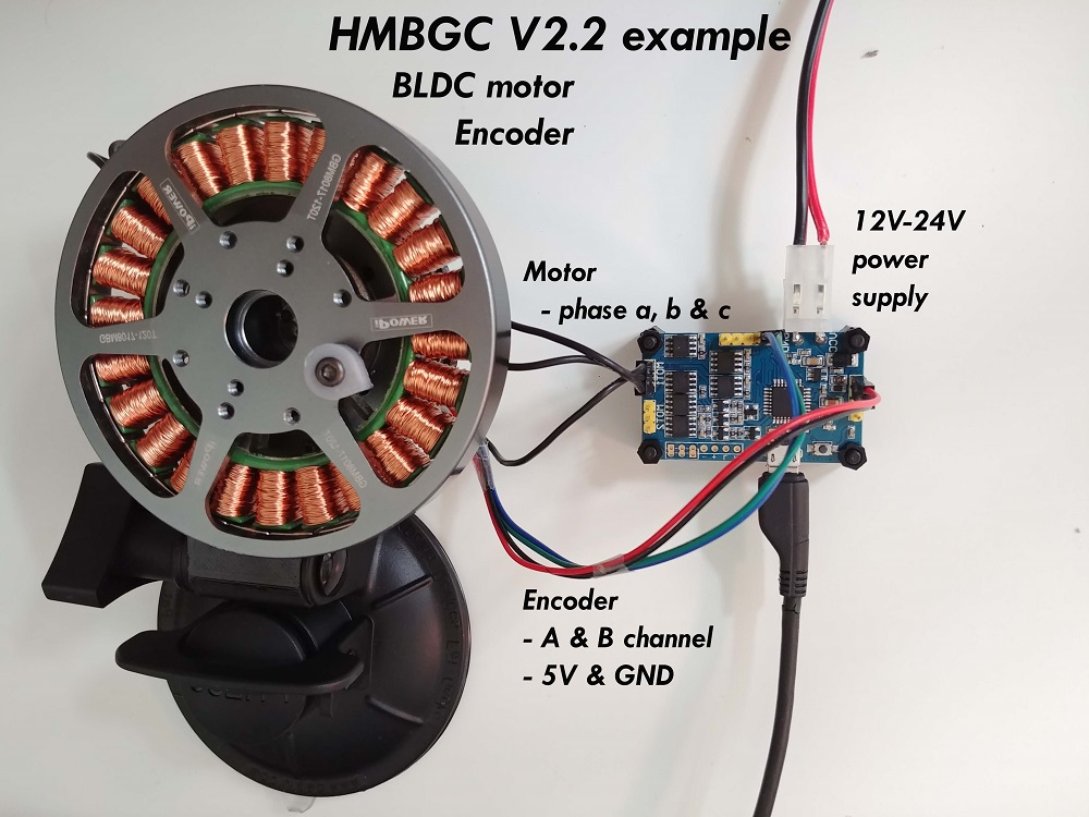
HMBGC V2.2 example
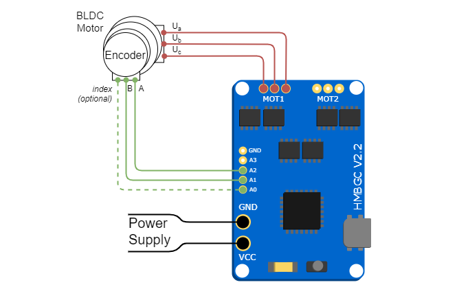
To use HMBGC controller for vector control (FOC) you need to connect motor to one of the motor terminals and connect the encoder to the analog pins. Following pictures show the schematic of the HMBGC board necessary connections and the one real example of the connection.
Encoder
Pinout restriction
HMBGC doesn't have access to the Arduino's external interrupt pins2and3, moreover the only pins we have access to are analog pinsA0-A7. Therefore we need to read the encoder channels using the software interrupt library, please check the encoder code implementation for more information.
Please see the HMBGC code example (HMBGC_example.ino) to test all the functionalities.
- Encoder channels
AandBare connected to the pinsA0andA1. - Optionally if your encoder has
indexsignal you can connect it to any available pin, figure shows pinA2.
Motor
- Motor phases
a,bandcare connected directly to the driver outputs - Motor terminal
M1uses Arduino pins9,10,11andM2uses3,5,6
HMBGC board doesn't support magnetic sensors because it doesn't have necessary SPI infrastructure.
Example connection