On this page
Stepper Driver - StepperDriver2PWM
This is the class which provides an abstraction layer of most of the common 2PWM stepper drivers out there. Basically any stepper driver board that can be run using 2PWM signals can be represented with this class. Examples:
There are two common 2 PWM stepper driver architectures
- With one direction pin per phase (
dirx) - With two direction pin per phase (
phxa&phxb)
Stepper driver with only one direction pin per phase has integrated inversion hardware in the driver itself which invert both PWM signal and direction pin. THese kinds of drivers are very common because they are intended for running dc motors with a simple PWM/direction interface. Basically, in order to run a stepper motor you need to combine two of these drivers. 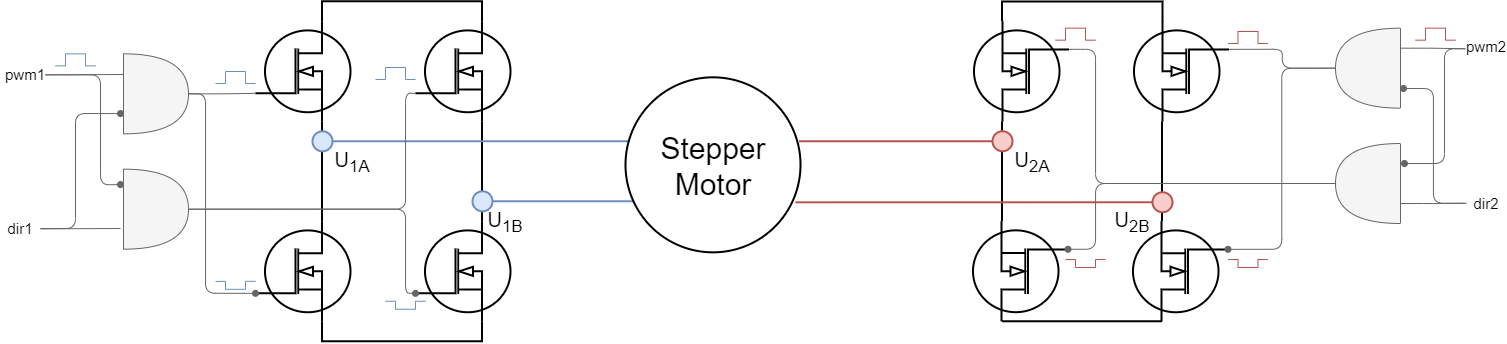
Stepper driver with two direction pins per phase had internal inversion hardware only for the PWM input but not for the direction input. And therefore it requires these inversions to be done outside, in software. You can imagine that StepperDriver2PWM class emulates the hardware circuits that are available in the one direction pin drivers shown above.

Step 1. Hardware setup
To create the interface to the stepper driver you need to specify the 2 PWM pin numbers, one for each motor phase. In addition to this you can choose to specify two direction pins per phase or just one. Finally you can add an optional enable pin for each phase en1 and en2.
For two direction pins per phase use the constructor:
// pwm1  PWM1 phase pwm pin
// in1   IN1A phase dir pins
// pwm2  PWM2 phase pwm pin
// in2   IN2A phase dir pins
// en1 enable pin phase 1 (optional input)
// en2 enable pin phase 2 (optional input)
// StepperDriver2PWM(int pwm1, int* in1, int pwm2, int* in2, int en1 = NOT_SET, int en2 = NOT_SET);
StepperDriver2PWM driver = StepperDriver2PWM(3, {4,5}, 10, {9,8}, 11, 12);
For only one direction pin per phase use the constructor:
//  StepperDriver2PWM( int pwm1,int dir1,int pwm2,int dir2, int en1 (optional), int en2 (optional))
//  - pwm1      - phase 1 pwm pin
//  - dir1      - phase 1 direction pin
//  - pwm2      - phase 2 pwm pin
//  - dir2      - phase 2 direction pin
//  - en1, en2  - enable pins (optional input)
StepperDriver2PWM driver = StepperDriver2PWM(3, 4, 5, 6, 11, 12);
📢 Here is a quick guide to choosing appropriate PWM pins for different MCU architectures see in docs.
Step 2.1 PWM Configuration
// pwm frequency to be used [Hz]
// for atmega328 either 4k or 32kHz
// esp32/stm32/teensy configurable
driver.pwm_frequency = 20000;
Here is a list of different microcontrollers and their PWM frequency and resolution used with the Arduino SimpleFOClibrary.
| MCU | default frequency | MAX frequency | PWM resolution | Center-aligned | Configurable freq |
|---|---|---|---|---|---|
| Arduino UNO(Atmega328) | 32 kHz | 32 kHz | 8bit | yes | yes (either 4kHz or 32kHz) |
| STM32 | 50kHz | 100kHz | 14bit | yes | yes |
| ESP32 | 40kHz | 100kHz | 10bit | yes | yes |
| Teensy | 50kHz | 100kHz | 8bit | yes | yes |
All of these settings are defined in the drivers/hardware_specific/x/x_mcu.cpp/h of the library source.
Step 2.2 Voltages
Driver class is the one that handles setting the PWM duty cycles to the driver output pins and it is needs to know the DC power supply voltage it is plugged to. Additionally driver class enables the user to set the absolute DC voltage limit the driver will be set to the output pins.
// power supply voltage [V]
driver.voltage_power_supply = 12;
// Max DC voltage allowed - default voltage_power_supply
driver.voltage_limit = 12;
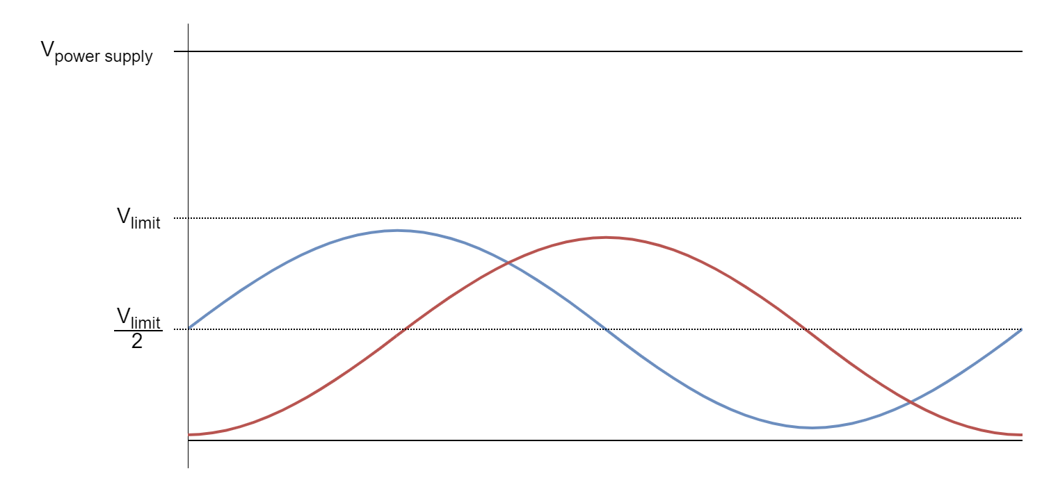
This parameter is used by the StepperMotor class as well. As shown on the figure above the once the voltage limit driver.voltage_limit is set, it will be communicated to the FOC algorithm in StepperMotor class and the phase voltages will be centered around the driver.voltage_limit/2.
Therefore this parameter is very important if there is concern of too high currents generated by the motor. In those cases this parameter can be used as a security feature.
Step 2.3 Initialisation
Once when all the necessary configuration parameters are set the driver function init() is called. This function uses the configuration parameters and configures all the necessary hardware and software for driver code execution.
// driver init
driver.init();
This function is responsible for:
- determining and configuring the hardware timer for PWM generation
- verifying that all provided pins can be used to generate PWM
- configuring the PWM channels
If for some reason the driver configuration fails this function will return 0 if everything went well the function will return 1. So we suggest you to check if the init function was executed successfully before continuing
Serial.print("Driver init ");
// init driver
if (driver.init())  Serial.println("success!");
else{
  Serial.println("failed!");
  return;
}
Enable debugging output
If you wish to see a more verbose debugging output of the driver configuration during the driver.init() and see more details about the driver configuration and possible errors, you can use the SimpleFOCDebug class. In order to enable the verbose debugging mode make sure to enable debugging before the driver.init() call, preferably at the top of the setup() function.
Serial.begin(115200); // to output the debug information to the serial
SimpleFOCDebug::enable(&Serial);
See more in the SimpleFOCDebug documentation.
Step 3. Using encoder in real-time
BLDC driver class was developed to be used with the SimpleFOClibrary and to provide the abstraction layer for FOC algorithm implemented in the StepperMotor class. But the StepperDriver4PWM class can used as a standalone class as well and once can choose to implement any other type of control algorithm using the BLDC driver.
FOC algorithm support
In the context of the FOC control all the driver usage is done internally by the motion control algorithm and all that is needed to enable is is just link the driver to the StepperMotor class.
// linking the driver to the motor
motor.linkDriver(&driver)
Standalone driver
If you wish to use the BLDC driver as a standalone device and implement your-own logic around it this can be easily done. Here is an example code of a very simple standalone application.
// Stepper driver standalone example
#include <SimpleFOC.h>


// Stepper driver instance
// StepperDriver2PWM(pwm1, in1a, in1b, pwm2, in2a, in2b, (en1, en2 optional))
StepperDriver2PWM driver = StepperDriver2PWM(3, 4, 5, 10 , 9 , 8 , 11, 12);

// StepperDriver2PWM(pwm1, dir1, pwm2, dir2,(en1, en2 optional))
// StepperDriver2PWM driver = StepperDriver2PWM(3, 4, 5, 6, 11, 12);

void setup() {

  // pwm frequency to be used [Hz]
  // for atmega328 fixed to 32kHz
  // esp32/stm32/teensy configurable
  driver.pwm_frequency = 30000;
  // power supply voltage [V]
  driver.voltage_power_supply = 12;
  // Max DC voltage allowed - default voltage_power_supply
  driver.voltage_limit = 12;

  // driver init
  driver.init();

  // enable driver
  driver.enable();

  _delay(1000);
}

void loop() {
    // setting pwm
    // phase A: 3V
    // phase B: 6V
    driver.setPwm(3,6);
}