Position control loop
This control loop allows you to move your motor to the desired angle in real-time. There are two different stategies for this control loop:
- Standard cascade angle control
- angle control loop is closing the loop around the velocity control loop, which is closing the loop around the torque control loop.
- Cascade angle control loop (Recommended)
- Non-cascade angle control
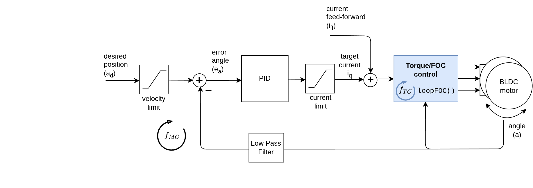
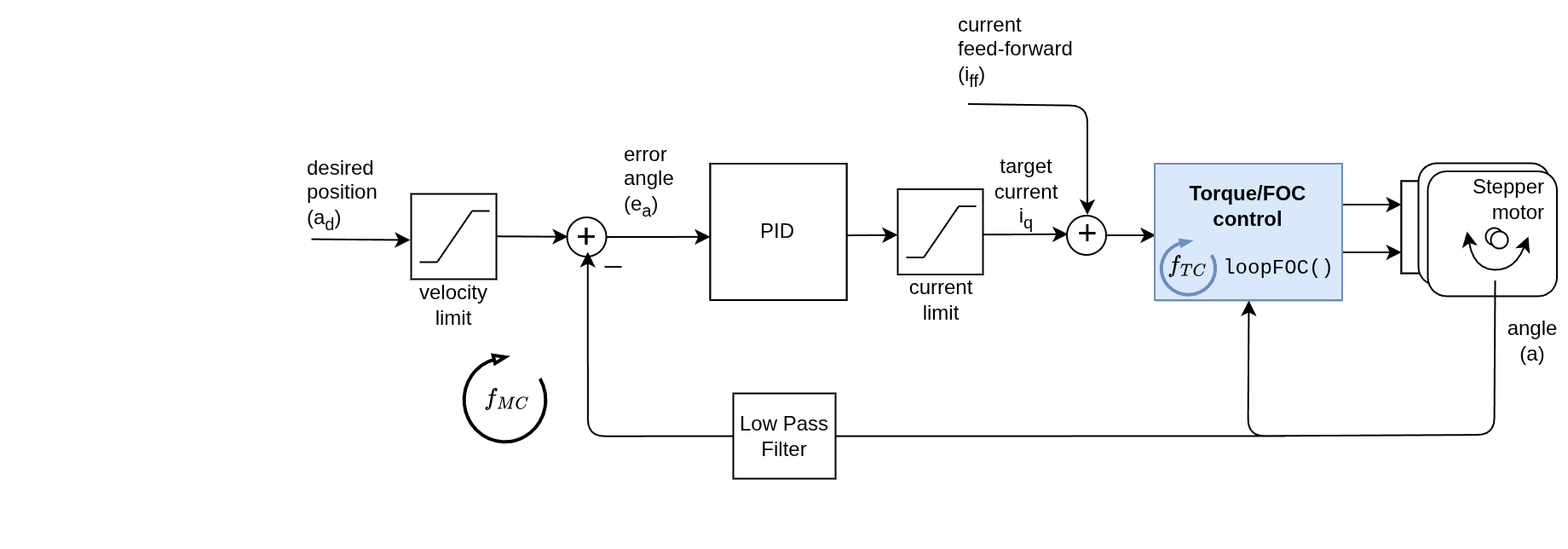
- angle control loop is closing the loop directly around the torque control loop.
- Non-cascaded angle control loop
You can enable the angle/position control loop by setting the controller variable of the motor to either MotionControlType::angle or MotionControlType::angle_nocascade depending on which strategy you want to use.
// set angle/position motion control loop
motor.controller = MotionControlType::angle; // standard cascade angle > velocity > torque control
// or
motor.controller = MotionControlType::angle_nocascade; // non-cascade angle control angle > torque control
You can test this algorithm by running the examples in motion_control/position_motion_control/ folder.
How it works
Cascade Position Control No-cascade Position Control
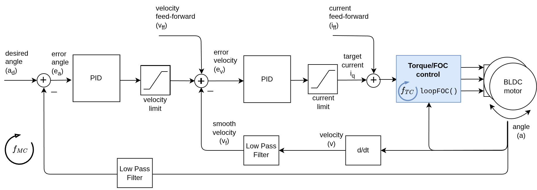
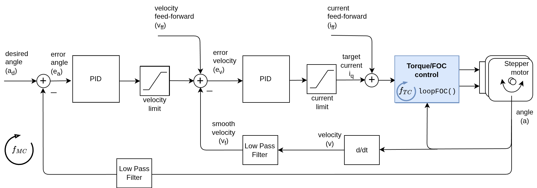
In Cascade position control the angle control loop is closing the loop around the velocity control loop, which is closing the loop around the torque control loop. This means that the angle controller will be setting the velocity target to the velocity controller, and then the velocity controller will be setting the torque target to the torque controller.
This angle control loop is therefore created by adding one more control loop in cascade on the velocity control loop like showed on the figure above. The loop is closed by using additional PID controller and an optional low pass filter. The controller reads the angle a from the motor (filters is optionally) and determines which velocity vd the motor should move to reach the desired angle ad set by the user. And then the velocity controller reads the current filtered velocity from the motor vf and sets the torque target (uq voltage or iq current) to the torque control loop, needed to reach the velocity vd, set by the angle loop.
Comparison of the two strategies
| Control Mode | Control Structure | Pros | Cons |
|---|---|---|---|
Cascade Position Control (angle) | P(angle) + PI (velocity) | ✔️ Safe Velocity Limits: Inherits the velocity_limit from the inner loop, preventing runaway speeds ✔️ Superior Stability: Dual-loop damping makes it much more robust against high-inertia loads . ✔️ High-Speed Precision: Provides better tracking performance at high velocities. | ❌ Tuning Complexity: Requires tuning two PID controllers (Velocity and Angle) plus the Low Pass Filter ❌ Not always intuitive: Conceptually hard to understand the interaction between the two loops. |
Non-Cascade Control (angle_nocascade) | PD or PID in special cases | ✔️ Low Latency: Direct path from angle to torque provides the fastest possible physical response ✔️ High Stiffness: Acts as a “Virtual Spring,” reacting instantly to disturbances. ✔️ Easier Setup: Only one PID controller to tune | ❌ Speed Instability: No internal velocity damping; can vibrate at high speeds ❌ No Velocity Limit: The motor can reach unsafe speeds instantly if the angle error is large (Runaway Risk) ❌ Inertia Sensitive: Hard to stabilize large masses without aggressive D gain tuning. |
Use-cases for Cascade Position Control:
- Robotic arms with varying loads and high precision requirements
- CNC machines where stability at high speeds is critical
- Applications where the the velocity needs to be limited or variable (e.g. conveyor belts, camera gimbals, safety concerns)
- Any application where safety and reliability are a concern
Go to Cascade Control (Recommended)
Use-cases for No-Cascade Position Control:
- Setups where there is an external mechanical damping or low inertia load
- Application where the motor fights gravity (e.g. vertical axis) and the load is never removed (I gain is important here)
- Systems simulating a spring-damper (PD controller)
Go to Non-Cascade Control (Advanced)