On this page
Steer by wire
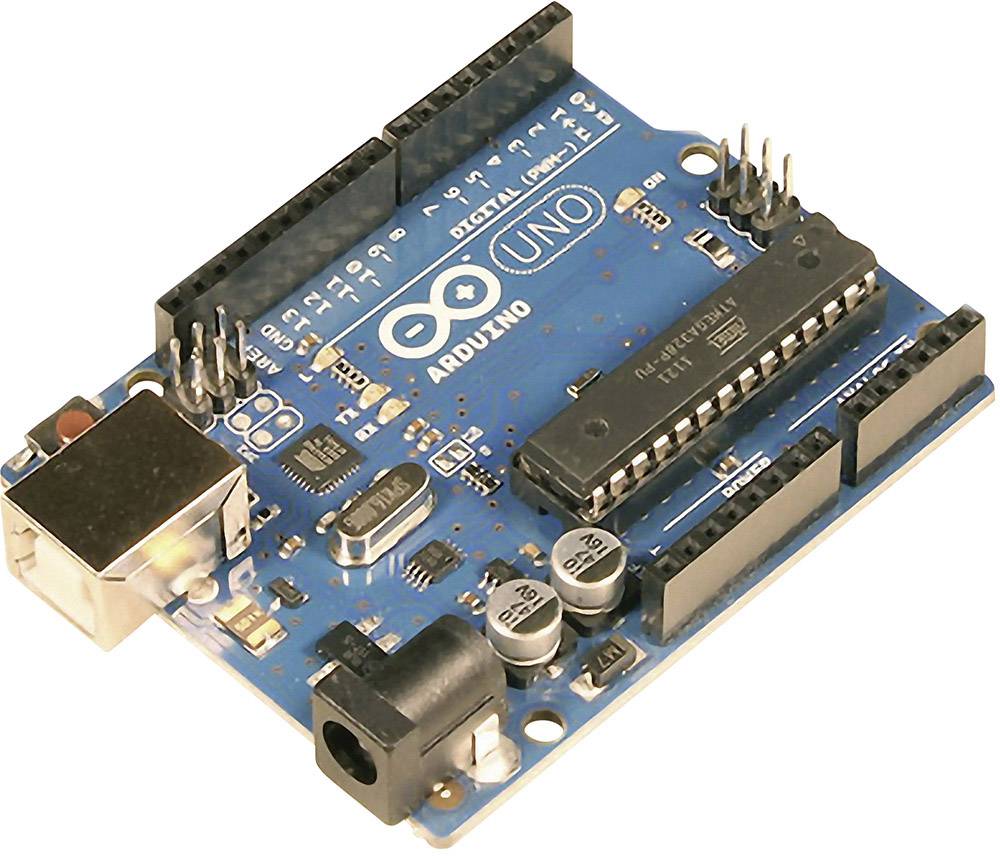
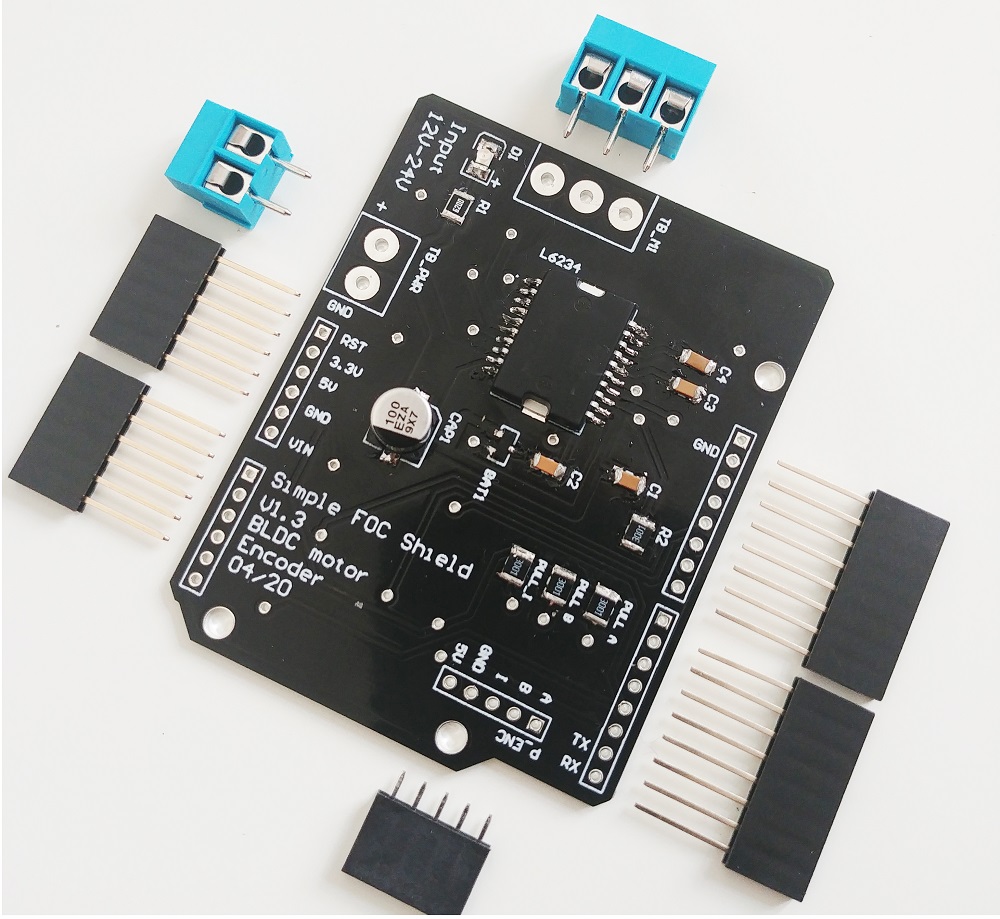
using SimpleFOCShield and Arduino UNO
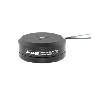
Download the STL file as well as STEP and solidworks project of the 3d printed stand for the IPower GM4108H-120T motor with the mount for the CUI amt103 encoder, used in the images and the Youtube video, here.
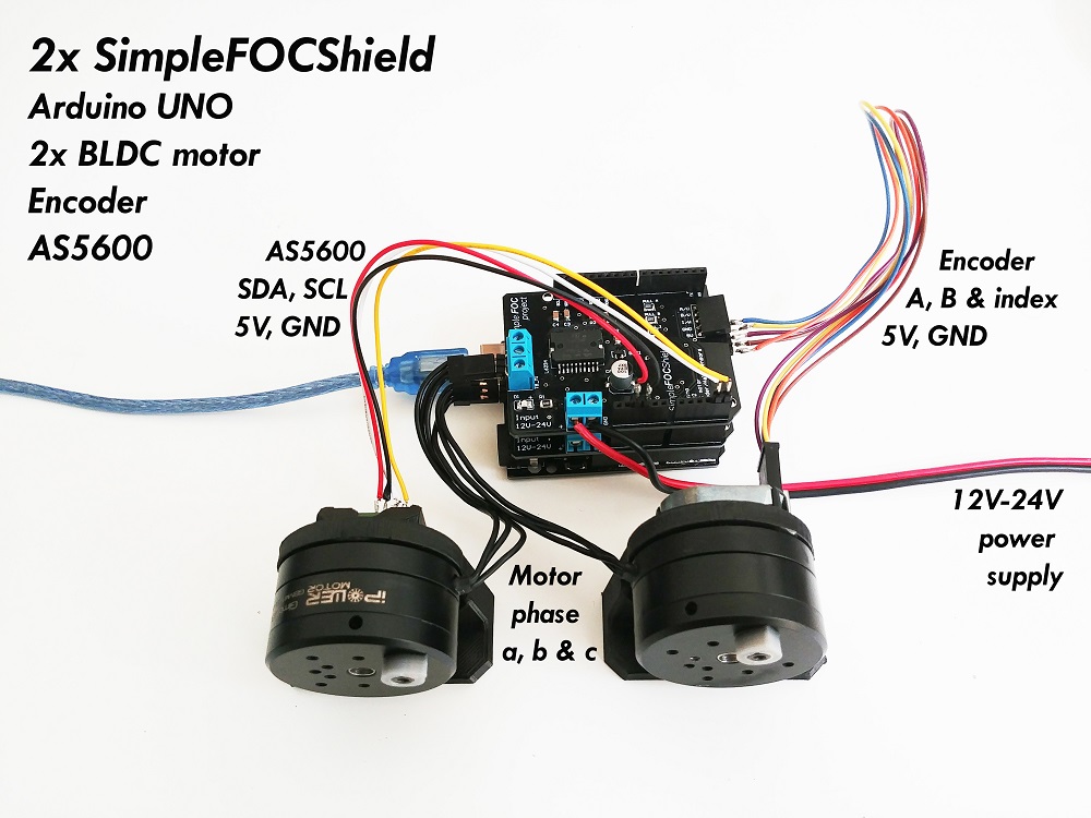
Connecting everything together
Here is a picture of the setup used in this project. Check the Arduino code to see the pin numbers that are used.
Arduino code
The code for this example is very simple. Since we use two BLDC motors we will need to use all 6 pwm Arduino UNO pins which means that we do not have enough hardware interrupt pins. Therefore we will need to use software interrupts. In this example, we will use PciManager library. It is very simple to use and I definitely recommend it, but it can be any other respectively.
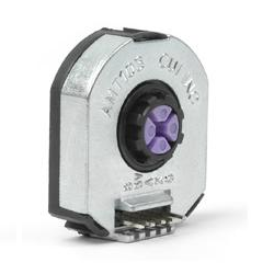
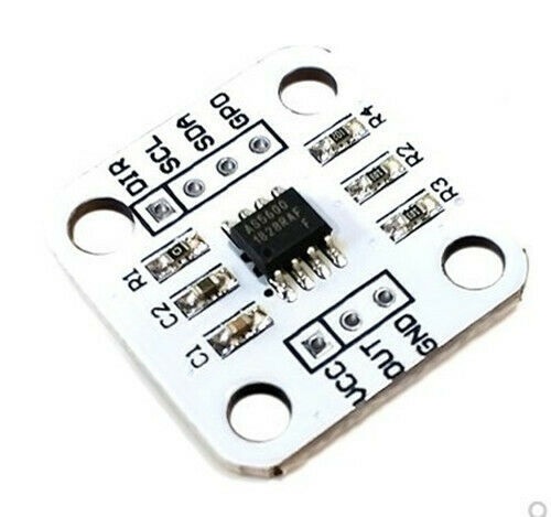
Both motors will be controlled in the torque/voltage control mode and one motor will have encoder as a sensor, the other will be using the magnetic sensor with I2C communication (AS5600). After both motors and sensors are initialized, no configuration is necessary, we can initialize FOC algorithm for both motors initFOC() and we are ready to go to real-time execution.
The smart stuff is placed in the loop() function. 😄
In order to maintain the virtual link in between two motors positions we write the code:
motor1.move( 5*(motor2.shaft_angle - motor1.shaft_angle));
motor2.move( 5*(motor1.shaft_angle - motor2.shaft_angle));
This control algorithm sets the voltage to the motors, proportional to their distance from the position of the other motor. Constant 5 is a scaling gain, it is found empirically and it will differ for each setup. But in general, the higher the number the stiffer the link, it will the more hard to introduce an offset in between motors positions.
And that is it, here is the full code of this example.
#include <SimpleFOC.h>
// software interrupt library
#include <PciManager.h>
#include <PciListenerImp.h>

BLDCMotor motor1 = BLDCMotor(11);
BLDCDriver3PWM driver1 = BLDCDriver3PWM(3, 10, 6, 7);
Encoder encoder1 = Encoder(A2, 2, 500, A0);
void doA1(){encoder1.handleA();}
void doB1(){encoder1.handleB();}
void doI1(){encoder1.handleIndex();}

// encoder interrupt init
PciListenerImp listenerA(encoder1.pinA, doA1);
PciListenerImp listenerB(encoder1.pinB, doB1);
PciListenerImp listenerI(encoder1.index_pin, doI1);

BLDCMotor motor2 =  BLDCMotor( 11);
BLDCDriver3PWM driver2 = BLDCDriver3PWM(9, 11, 5, 8);
MagneticSensorI2C sensor2 = MagneticSensorI2C(0x36, 12, 0x0E, 4);

void setup() {

  // initialise encoder hardware
  encoder1.init();
  // interrupt initialization
  PciManager.registerListener(&listenerA);
  PciManager.registerListener(&listenerB);
  PciManager.registerListener(&listenerI);
  // link the motor to the sensor
  motor1.linkSensor(&encoder1);

  // init driver
  driver1.init();
  // link driver
  motor1.linkDriver(&driver1);

  // set control loop type to be used
  motor1.controller = MotionControlType::torque;
  // initialise motor
  motor1.init();
  // align encoder and start FOC
  motor1.initFOC();

  // initialise magnetic sensor hardware
  sensor2.init();
  // link the motor to the sensor
  motor2.linkSensor(&sensor2);
  // init driver
  driver2.init();
  // link driver
  motor2.linkDriver(&driver2);
  // set control loop type to be used
  motor2.controller = MotionControlType::torque;
  // initialise motor
  motor2.init();
  // align encoder and start FOC
  motor2.initFOC();

  Serial.println("Steer by wire ready!");
  _delay(1000);
}

void loop() {
  // iterative setting FOC phase voltage
  motor1.loopFOC();
  motor2.loopFOC();

  // virtual link code
  motor1.move( 5*(motor2.shaft_angle - motor1.shaft_angle));
  motor2.move( 5*(motor1.shaft_angle - motor2.shaft_angle));

}
Haptic velocity control
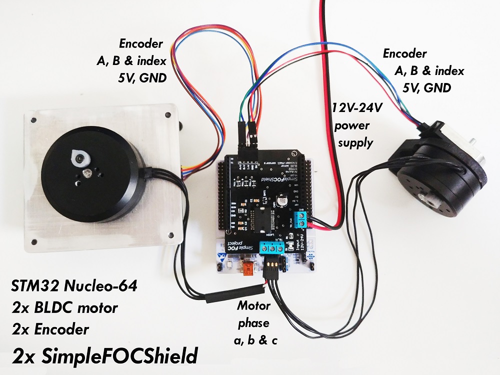
using SimpleFOCShield and Stm32 Nucleo-64
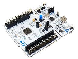
Connecting everything together
Here is a picture of the setup used in this project. Check the Arduino code to see the pin numbers that are used.
Arduino code
In this example we will be using the Nucleo-64 board and two BLDC motors with encoders. Since Nucleo doesn’t have problems with hardware interrupts (every pin can be external interrupt pin), there is no complications in code due to usage of 6 pwm pins. The only difference in between Nucleo and Arduino UNO is that Nucleo pin cannot use its pin 11 for PWM so we need to use pin 13 instead. The rest of the code is very straight forward.
We define two motors and two encoders and link them together.
#include <SimpleFOC.h>

BLDCMotor motor1 = BLDCMotor(11);
BLDCDriver3PWM driver1 = BLDCDriver3PWM(9, 6, 5, 7);
Encoder encoder1 = Encoder(A1, A2, 8192);
void doA1(){encoder1.handleA();}
void doB1(){encoder1.handleB();}


BLDCMotor motor2 = BLDCMotor(11);
BLDCDriver3PWM driver2 = BLDCDriver3PWM(3, 13, 10, 8);
Encoder encoder2 = Encoder(A3, 2, 500);
void doA2(){encoder2.handleA();}
void doB2(){encoder2.handleB();}


void setup() {

  // initialise encoder hardware
  encoder1.init();
  encoder1.enableInterrupts(doA1,doB1);

  encoder2.init();
  encoder2.enableInterrupts(doA2,doB2);
  // link the motor to the sensor
  motor1.linkSensor(&encoder1);
  motor2.linkSensor(&encoder2);

  // config drivers
  driver1.init();
  driver2.init();

  // link the motor to the driver
  motor1.linkDriver(&driver1);
  motor2.linkDriver(&driver2);
}
void loop(){}
Then we define the motion control to be voltage for one motor and the velocity for the other:
// set control loop type to be used
motor1.controller = MotionControlType::torque;
motor2.controller = MotionControlType::velocity;
Additionally we introduce a bit higher degree of filtering by augmenting Tf value and rise a bit the integral gain I as well for better following.
// augment filtering
motor2.LPF_velocity.Tf = 0.02;
// rise I gain
motor2.PID_velocity.I = 40;
And to finish the setup() we just initialize the motors and FOC algorithm.
The smart stuff is again in the the loop() function. The virtual link code looks like this:
// virtual link code
motor1.move(5*(motor2.shaft_velocity/10 - motor1.shaft_angle));
motor2.move(10*motor1.shaft_angle);
This control strategy basically says that the target velocity of the motor2 will be proportional to the position of the motor1. On the other hand, it sets the voltage to the motor1 proportional to the difference in between the difference on the velocity of the motor2 and position of the motor1. This creates a virtual link in between those two variables.
Constant 5 is the scaling gain with the same role as in the previous example. It will just make the motor1 be more or less responsive while following the motor2 velocity and it will want to maintain the difference in 0.
Constant 10 is a bit different. It is a scaling factor which helps to better map velocity to the positon. For example in the example we are using the motor2 has maximal velocity of 60rad/s, but we don’t want our gauge to rotate 10 rotations to show this velocity. we would like it to rotate maximally 1 rotation ~6rad therefore the constant 10. But in your case maybe you will be running a drone motor, which turns with thousands of RPM and you might want to have even larger scaling 100 or even a 1000. On the other hand, maybe you will want to have a very precise slow moving motor which will go under 1 radian/s. And you will want to go to the values of ~0.1 or even less. Therefore this will depend on your application and the precisions you will need to have.
One more interesting thing to notice is that this scaling factor can be variable, so you could change it in real-time as well.
Here is the full example code:
#include <SimpleFOC.h>

BLDCMotor motor1 = BLDCMotor(11);
BLDCDriver3PWM driver1 = BLDCDriver3PWM(9, 6, 5, 7);
Encoder encoder1 = Encoder(A1, A2, 8192);
void doA1(){encoder1.handleA();}
void doB1(){encoder1.handleB();}


BLDCMotor motor2 = BLDCMotor(11);
BLDCDriver3PWM driver2 = BLDCDriver3PWM(3, 13, 10, 8);
Encoder encoder2 = Encoder(A3, 2, 500);
void doA2(){encoder2.handleA();}
void doB2(){encoder2.handleB();}

void setup() {

  // initialise encoder hardware
  encoder1.init();
  encoder1.enableInterrupts(doA1,doB1);

  encoder2.init();
  encoder2.enableInterrupts(doA2,doB2);
  // link the motor to the sensor
  motor1.linkSensor(&encoder1);
  motor2.linkSensor(&encoder2);

  // config drivers
  driver1.init();
  driver2.init();
  // link the motor to the driver
  motor1.linkDriver(&driver1);
  motor2.linkDriver(&driver2);

  // set control loop type to be used
  motor1.controller = MotionControlType::torque;
  motor2.controller = MotionControlType::velocity;

  motor2.LPF_velocity.Tf = 0.02;
  motor2.PID_velocity.I = 40;

  // use monitoring with serial for motor init
  // monitoring port
  Serial.begin(115200);
  // enable monitoring
  motor1.useMonitoring(Serial);
  motor2.useMonitoring(Serial);

  // initialise motor
  motor1.init();
  motor2.init();
  // align encoder and start FOC
  motor1.initFOC();
  motor2.initFOC();

  Serial.println("Interactive gauge ready!");
  _delay(1000);
}


void loop() {
  // iterative setting FOC phase voltage
  motor1.loopFOC();
  motor2.loopFOC();

  // iterative function setting the outter loop target
  motor1.move(5*(motor2.shaft_velocity/10 - motor1.shaft_angle));
  motor2.move(10*dead_zone(motor1.shaft_angle));

}

float dead_zone(float x){
  return abs(x) < 0.2 ? 0 : x;
}