On this page
Cascade position control loop
This control loop allows you to set the position/angle to your motor in real-time. This mode is enabled by:
// set angle/position motion control loop
motor.controller = MotionControlType::angle;
You can find a couple of examples in the examples/motion_control/position_motion_control/ library folder.
How it works
The angle/position control closes the control loop around the velocity control loop. And the velocity control closes the control loop around the torque control, regardless which one it is. If it is the voltage mode, the velocity motion control will set the the torque command using the voltage \(u_q\):
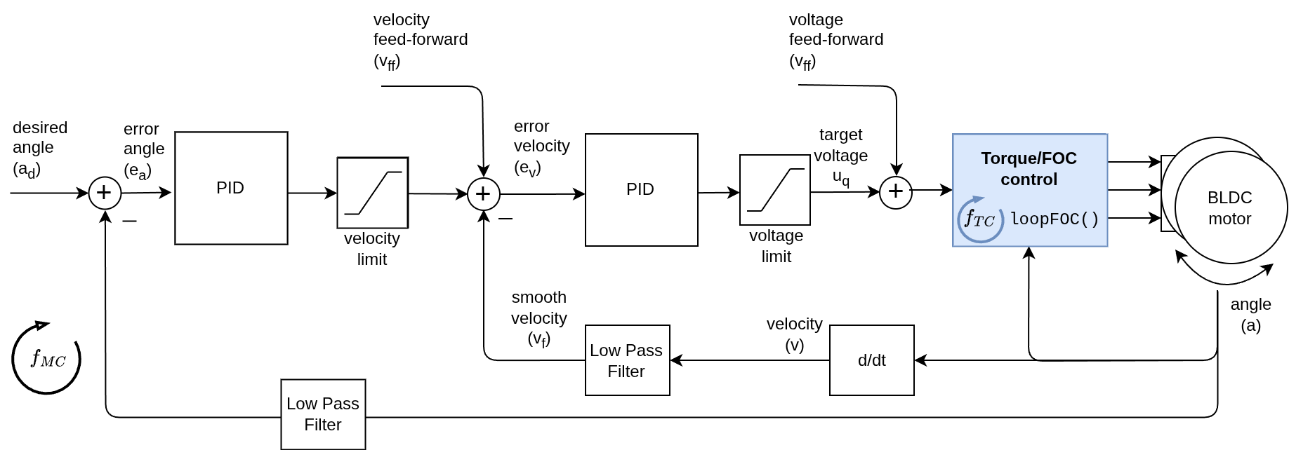
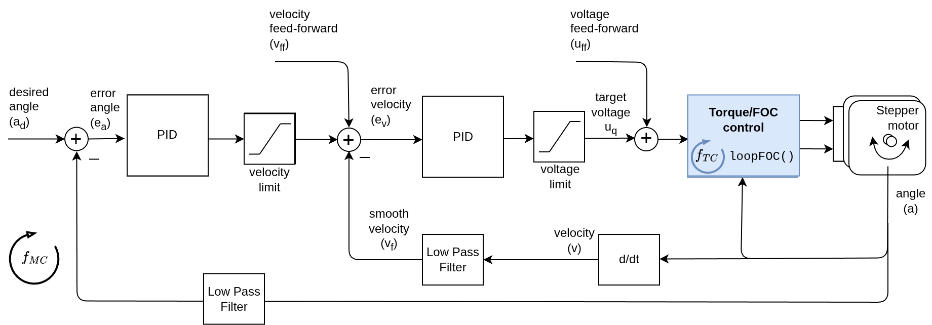
And if it is any of the current torque control modes (FOC current, DC current or estimated current), the angle motion control will be setting the target current \(i_q\) to the torque controller:
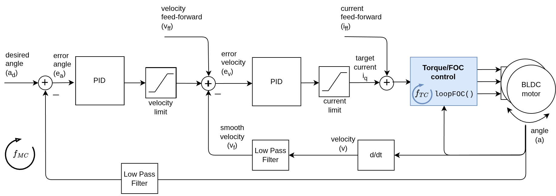
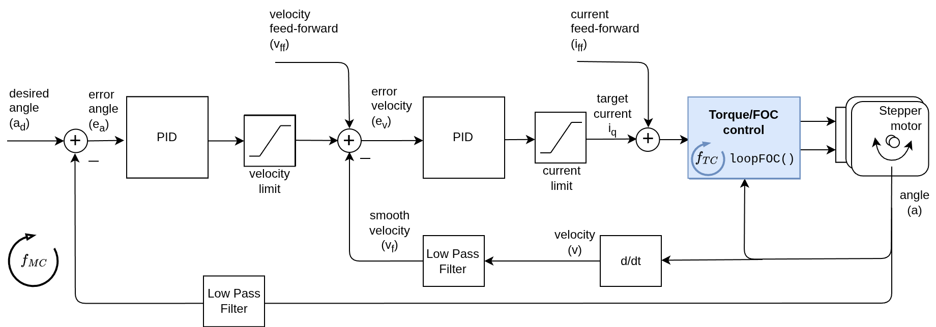
The angle control loop is therefore created by adding one more control loop in cascade on the velocity control loop like showed on the figure above. The loop is closed by using additional PID controller and an optional low pass filter. The controller reads the angle \(a\) from the motor (filters is optionally) and determines which velocity \(v_d\) the motor should move to reach the desired angle \(a_d\) set by the user. And then the velocity controller reads the current filtered velocity from the motor \(v_f\) and sets the torque target (\(u_q\) voltage or \(i_q\) current) to the torque control loop, needed to reach the velocity \(v_d\), set by the angle loop.
Control parameters
To tune this control loop, it is recomemended to start from the lowest level loop (torque control) and then move up to the velocity loop and then finish with the angle loop. The parameters of the lower level loops will affect the performance of the angle control loop, so it is important to have them tuned before tuning the angle loop.
Torque loop guidance
The torque loop parameters are the same ones used in the torque control page. In many cases you will tune them once and will not need to change them again. Some torque control modes are simpler than the others, for example the voltage mode has no parameters to tune, while the FOC current mode has more parameters to tune but it can give you better performance.
Read more about torque control modes and parameters
Velocity loop (inner loop) guidance
The velocity loop parameters are the same ones used in the velocity control page. As for torque control in most cases you will tune them once and reuse the same values here. The rule of thumb if you already tuned the velocity control loop is:
- Lower proportional gain
Pif you see vibrations. - You often won’t need to change
IorDfor position control.
Read more about velocity control loop and parameters See the velocity loop tuning guide
Example parameters for the velocity loop:
// velocity PID controller parameters
// default P=0.5 I = 10 D =0
motor.PID_velocity.P = 0.2;
motor.PID_velocity.I = 20;

// velocity low pass filtering
motor.LPF_velocity.Tf = 0.01; // seconds - default 0.005s
Angle loop (outer loop) guidance
The angle loop is typically a simple P controller, with optional limits for smoothness.
- Start with only
P(I=D=0). - Increase
Puntil you get a responsive motion without oscillation. - If you see overshoot, you can try adding a small
Dgain to dampen it, but often it’s not needed.
Example parameters for the angle loop:
// angle PID controller
motor.P_angle.P = 10; // default P=20
Additional Advanced Parameters
The P gain is the most important parameter to tune and the one that will have the biggest impact on the performance of the cascaded position control loop. Apart from the PID gains, there are several other parameters that can be set for the velocity control loop for specific use cases
-
Output Ramp: This is a rate limiter variable. The parameter limits how quickly the PID controller’s output can change, helping to reduce system jerkiness. It is measured in Radians per second \(\frac{rad}{s^2}\). For example, a setting of
motor.P_angle.output_ramp=1means the output of the angle loop (target velocity) cannot change faster than 1 \(\frac{rad}{s}\) in one second. This parameter in this context limits the acceleration of the motor. Setting it toNOT_SETor0disables this limit (default is0). -
Limit: This parameter restricts the PID controller’s output (the maximal target velocity the angle loop can command) measured in Radians / s \(\frac{rad}{s}\). Setting it to
NOT_SETremoves the limit. This limit will be automatically set usingupdateVelocityLimit()but the user can manually adjust it for different limits. -
Sampling Time: This sets the PID controller’s sampling time in seconds [s]. The default is
NOT_SET, allowing the PID to calculate the sampling time based on the time between calls to theP_anglecontroller. Specifying a value can save processing time, but it should closely match the actual sampling time. For instance, ifmotor.move()runs at1000Hz, set the sampling time to0.001seconds.
Motion control frequency
By default, the motion control loop runs at the same frequency \(f_{MC}\) as the torque control loop \(f_{TC}\), which is typically around 1-10 kHz. However, in some cases, you may want to run the motion control loop at a lower frequency than the torque control loop. In that case you can use the motion_downsampling parameter of the motor.
For example, setting motion_downsampling to 10 will run the velocity control loop at 100 Hz while the torque control loop runs at 1 kHz:
motor.motion_downsampling = 10; // run velocity loop at 10 times lower frequency than torque loop
In other words, the velocity control loop will run at a frequency of \(f_{MC} = \frac{f_{TC}}{\texttt{motion_downsampling}}\), meaning that the motor.move() function will be called every motion_downsampling number of motor.loopFOC() calls.
Control parameters overview
| Parameter | Variable | Description | Default Value | Unit |
|---|---|---|---|---|
Velocity P | motor.PID_velocity.P | Responsiveness of the velocity loop. | 0.5 | \(\frac{Vs}{rad}\) or \(\frac{As}{rad}\) |
Velocity I | motor.PID_velocity.I | Disturbance rejection for velocity. | 10.0 | \(\frac{V}{rad}\) or \(\frac{A}{rad}\) |
Velocity D | motor.PID_velocity.D | Damping / overshoot control. | 0.0 | \(\frac{Vs^2}{rad}\) or \(\frac{As^2}{rad}\) |
Velocity filter Tf | motor.LPF_velocity.Tf | Low-pass filtering of velocity. | 0.005 | \(s\) |
Angle P | motor.P_angle.P | Responsiveness of position control. | 20.0 | \(\frac{1}{s}\) |
Angle filter Tf | motor.LPF_angle.Tf | Low-pass filtering of angle. | 0.0 | \(s\) |
| Angle output ramp | motor.P_angle.output_ramp | Acceleration limit. | 1e6 | \(\frac{rad}{s^2}\) |
| Motion downsampling | motor.motion_downsampling | Run angle loop at lower frequency than torque loop. | 1 | - |
For more theory about this approach and the source code documentation check the digging deeper section.
Dig deeper into motion control theory
Velocity & Torque Limits
One of the main benefits of this cascaded control is that it allows you to set and modify in real-time the limits on the velocity and torque of the motor.
- Velocity limit: allows you to choose how fast the motor can move to reach the target position. The lower the limit the slower the motor will be, but it will also be more smooth and less likely to overshoot.
- Torque limit: allows you to choose how much torque the motor can apply to reach the target position. The lower the limit the more backdriveable the motor will be, but it will also be less responsive and less able to resist disturbances.
You can set the velocity limit of the position control loop and the torque limits by using the following functions:
// set velocity limit of the position control loop
motor.updateVelocityLimit(10); // rad/s - default 20

// setting the torque limits
// either current
motor.updateCurrentLimit(2); // Amps - default 2A
// or voltage
motor.updateVoltageLimit(10); // Volts -   default 12V
Target & Feed-forward terms
The position control loop uses the target angle as its main reference. You can set or update it at runtime:
// set target angle (radians)
motor.target = 1.57; // ~90 deg
Position/angle units
The units of the
motor.targetvariable in angle control modes are radians \(rad\). If you want to use different units, like turns or degrees, you will need to convert them accordingly.
The cascade controller also supports feed-forward terms to improve tracking for dynamic motion profiles.
| Term | Variable | Description | Unit |
|---|---|---|---|
| Target angle | motor.target | Target angle for the position controller. | \(rad\) |
| Velocity feed-forward | motor.feed_forward_velocity | Adds a constant velocity to help tracking. | \(\frac{rad}{s}\) |
| Current feed-forward | motor.feed_forward_current | Adds a constant current to the torque loop (current-based torque modes). | \(A\) |
| Voltage feed-forward | motor.feed_forward_voltage | Adds a constant voltage to the torque loop (voltage or current modes). | \(V\) |
// velocity feed-forward
motor.feed_forward_velocity = 1.0; // add 1 Rad/s to the velocity
// current feed-forward
motor.feed_forward_current.q = 0.5; // add 0.5 A to the
// voltage feed-forward
motor.feed_forward_voltage.q = 1.0; // add 1 V to the voltage
Be careful with feed-forward terms
The feed-forward terms can be very useful for improving the performance of the control loop, but they can also cause instability if not used carefully. They are intended for advanced users who have a good understanding of the system and the control loop. If you are not sure about how to use them, it is recomended not to use them.
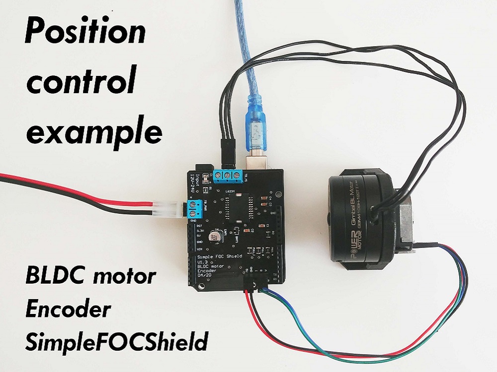
Position control example code
This is a very basic example of the position motion control program, based on voltage torque control with the complete configuration. When running this code the motor will move in between angles -1 RAD and 1 RAD each 1 sec.
#include <SimpleFOC.h>

// motor instance
BLDCMotor motor = BLDCMotor(11);
// driver instance
BLDCDriver3PWM driver = BLDCDriver3PWM(9, 10, 11, 8);

// encoder instance
Encoder encoder = Encoder(2, 3, 500);
// channel A and B callbacks
void doA(){encoder.handleA();}
void doB(){encoder.handleB();}

void setup() {

  // initialize encoder sensor hardware
  encoder.init();
  encoder.enableInterrupts(doA, doB);
  // link the motor to the sensor
  motor.linkSensor(&encoder);

  // driver config
  driver.voltage_power_supply = 12; // V
  driver.init();
  motor.linkDriver(&driver);

  // set motion control loop to be used
  motor.controller = MotionControlType::angle;
  // torque control mode - voltage mode
  motor.torque_controller = TorqueControlType::voltage;

  // velocity PID controller parameters
  // default P=0.5 I = 10 D =0
  motor.PID_velocity.P = 0.2;
  motor.PID_velocity.I = 20;

  // velocity low pass filtering
  // default 5ms - try different values to see what is the best.
  // the lower the less filtered
  motor.LPF_velocity.Tf = 0.01;

  // angle P controller -  default P=20
  motor.P_angle.P = 20;

  //  maximal velocity of the position control
  // default 20
  motor.updateVelocityLimit(10); // Rad/s
  // torque limits
  motor.updateVoltageLimit(4); // Volts

  // use monitoring with serial
  Serial.begin(115200);
  // comment out if not needed
  motor.useMonitoring(Serial);

  // initialize motor
  motor.init();
  // align encoder and start FOC
  motor.initFOC();


  Serial.println("Motor ready.");
  _delay(1000);
}

// angle set point variable
float target_angle = 1;
// timestamp for changing direction
long timestamp_us = _micros();

void loop() {

  // each one second
  if(_micros() - timestamp_us > 1e6) {
      timestamp_us = _micros();
      // inverse angle
      target_angle = -target_angle;
  }

  // main FOC algorithm function
  motor.loopFOC();

  // Motion control function
  motor.move(target_angle); // radians
}
Project examples
Here is one project example which uses position control and describes the full hardware + software setup needed.
Find more projects in the example projects section.