On this page
Tuning the Current Control Loop
BLDC motors Stepper motors Hybrid Stepper motors
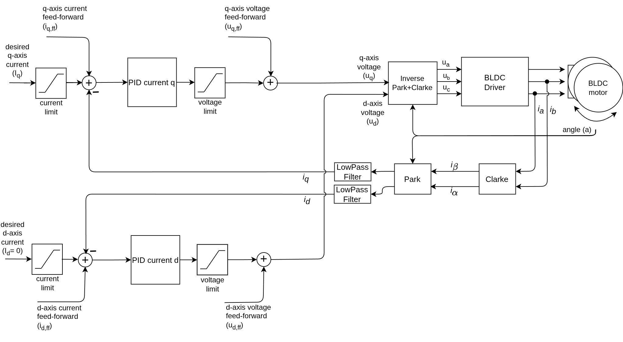
Tuning the current control loop is the foundation for stable torque control. There are many ways of doing it, depending on how well the motor model is known and how much time you want to spend on it.
In this guide we will cover the method that is implemented in the library, which is based on a simple motor model and a target bandwidth. It is a good starting point for most users, as it provides a reasonable starting parameters, sufficient for most applications.
Suggested tuning strategy
The library implements a pole placement method based on a simple RL model of the motor phase current dynamics.
Real components Frequency domain
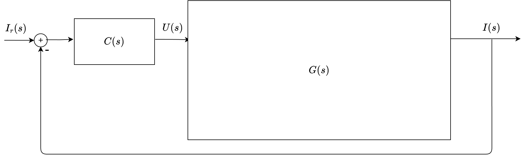
The motor phase current dynamics (per axis) can be approximated by an RL plant:
\[G(s)=\frac{I(s)}{V(s)}=\frac{1}{L s + R}\]The library targets a closed-loop bandwidth \(\omega_{bw}=2\pi f_{bw}\) and chooses a PI controller:
\[C(s)=K_p + \frac{K_i}{s}\]Then we can use pole placement to find the controller gains that approximately place the closed-loop poles at the desired bandwidth (\(-\omega_{bw}\)). The resulting gains are:
\[P_{d,q} = K_p = L_{d,q}\,(2\pi f_{bw}), \qquad I_{d,q} = K_i = R\,(2\pi f_{bw})\]This method relies on the simplified/idealised motor model and the assumption about the bandwidth, so it may not give perfect results in all cases. But it is a good starting point for most users, and can be further fine-tuned if needed.
See the PID implementation details.
The current filters can also be set by using the knowledge about the desired bandwidth. Typically with a cutoff a couple of times higher than the bandwidth (suggested \(5\times\)):
\[T_f = \frac{1}{2\pi\,(5 f_{bw})}\]See the LPF implementation details.
Pole placement derivation
This pole-placement method is relatively well-known in the control community and is a common approach for tuning current loops in motor control. It provides a systematic way to choose controller gains without too much trial and error, as long as the motor parameters are reasonably accurate. Example use in scientific literature. Section III.A..
The open-loop transfer function is:
\[L(s) = C(s) \cdot G(s) = \left(K_p + \frac{K_i}{s}\right) \cdot \frac{1}{L s + R}\]Combining into a single fraction:
\[L(s) = \frac{K_p s + K_i}{s(L s + R)} = \frac{K_p s + K_i}{L s^2 + R s}\]The closed-loop transfer function is:
\[H(s) = \frac{L(s)}{1 + L(s)} = \frac{K_p s + K_i}{L s^2 + (R + K_p) s + K_i}\]The characteristic polynomial of the closed loop is:
\[P_{cl}(s) = L s^2 + (R + K_p) s + K_i\]To place both poles at \(s = -\omega_{bw}\), we want:
\[P_{cl}(s) = L(s + \omega_{bw})^2 = L(s^2 + 2\omega_{bw} s + \omega_{bw}^2)\]Expanding:
\[P_{cl}(s) = L s^2 + 2L\omega_{bw} s + L\omega_{bw}^2\]Matching coefficients with the closed-loop characteristic polynomial:
\[\begin{align} \text{coeff of } s : & \quad R + K_p = 2L\omega_{bw} \\ \text{const term:} & \quad K_i = L\omega_{bw}^2 \end{align}\]We also want the PI controller to cancel the plant pole at \(s = -R/L\). This happens when:
\[\frac{K_i}{K_p} = \frac{R}{L}\]Substituting \(K_i = L\omega_{bw}^2\) into this equation allows to express both \(K_p\) and \(K_i\) in terms of the motor parameters and the desired bandwidth:
\[K_i = L\omega_{bw}^2, \qquad K_p = \frac{L^2 \omega_{bw}^2}{R}\]These are the gains that would place the poles at the desired location while also canceling the plant pole. However, this can lead to gains that are very sensitive with respect to the bandwidth and the motor parameters (since gains depens on the square of the bandwidth \(\omega_{bw}^2\) and the inductance \(L^2\)).
In order to simplify the design and make it more robust, an assumption is made that the bandwidth is chosen such that \(L\omega_{bw} \approx R\), which is a reasonable condition for typical motor control applications. Under this assumption, the gains simplify to:
\[K_p = L\,\omega_{bw}, \qquad K_i = R\,\omega_{bw}\]This new gains have linear relationship with the bandwidth and the motor parameters, making it easier to tune and less sensitive to parameter variations. The resulting closed-loop poles will be close to the desired bandwidth, providing a good balance between performance and robustness.
So that is why we suggest these gains as a starting point for tuning the current loop.
\[P_{d,q} = K_p = L_{d,q}\,(2\pi f_{bw}), \qquad I_{d,q} = K_i = R\,(2\pi f_{bw})\]Of course this method relies on the simplified motor model and the assumption about the bandwidth, so it may not give perfect results in all cases. But it is a good starting point for most users, and can be further fine-tuned if needed.
Don’t have motor parameters?
If you cannot find motor parameters in the datasheet and you have current sensing available, you can use the library’s characteriseMotor() function to estimate the phase resistance and inductance. This will allow you to use the tuning method described above without needing to measure the parameters manually.
// Characterise the motor to estimate parameters
// - requires current sensing
// - runs a series of tests to measure current response to voltage steps
// - voltage should be chosen to be:
//     - high enough voltage to get a good current response, but not too high to avoid overheating the motor
//     - can use the `motor.voltage_sensor_align` parameter as a safe starting voltage for characterisation
float characterisation_voltage = 1.0f; // volts or motor.voltage_sensor_align (safe default)
motor.characteriseMotor(characterisation_voltage); // voltage in volts
You can also measure the phase resistance manually with a multimeter, and then use the assumption that the inductance is typically in the range of 1 mH to 10 mH for small BLDC motors, or use typical values from similar motors as a starting point.
See how to measure the phase resistance in the practical guides.
Choosing a bandwidth
Pick a current-loop bandwidth that is well below your loopFOC() frequency. A good starting point is:
Example: if loopFOC() runs at 2 kHz, start with \(f_{bw}=100\text{–}200\text{ Hz}\).
Example code
void setup() {
  ...

  motor.phase_resistance = 0.5; // Ohms
  motor.axis_inductance = {0.001, 0.001}; // Henries

  float bandwidth = _2PI*150.0; // Hz
  // PID tunning
  motor.PID_current_q.P = motor.axis_inductance.q * bandwidth;
  motor.PID_current_q.I = motor.phase_resistance * bandwidth;
  motor.PID_current_d.P = motor.axis_inductance.d * bandwidth;
  motor.PID_current_d.I = motor.phase_resistance * bandwidth;
  // LPF tunning
  motor.LPF_current_d.Tf = 1.0f / (bandwidth * 5.0f);
  motor.LPF_current_q.Tf = 1.0f / (bandwidth * 5.0f);

  ...
}
SimpleFOClibrary also provides a helper function motor.tuneCurrentController(bandwidth) that implements this tuning strategy automatically based on the motor parameters and the desired bandwidth. It also includes some sanity checks to ensure the bandwidth is reasonable given the loopFOC() frequency and that the motor parameters are set (or can be characterised if current sensing is available).
Automatic current PI tuning
The library function motor.tuneCurrentController(bandwidth) implements the tuning logic below:
int FOCMotor::tuneCurrentController(float bandwidth) {
  // Sanity check the bandwidth
  if (bandwidth <= 0.0f) return 1;
  // Ensure bandwidth is below 0.5xfrequency of loopFOC (Nyquist limit)
  // - it only works after loop() has been running for a few iterations to measure loop time
  if (loopfoc_time_us && bandwidth > 0.5f * (1e6f / loopfoc_time_us)) return 2;

  // If motor parameters are not set, try to characterise the motor (if current sense is available)
  if (!_isset(phase_resistance) || (!_isset(phase_inductance) && !_isset(axis_inductance.q))) {
    if (characteriseMotor(voltage_sensor_align)) return 3;
  } else if (_isset(phase_inductance) && !(_isset(axis_inductance.q))) {
    axis_inductance = {phase_inductance, phase_inductance};
  }

  // Calculate PI gains based on motor parameters and desired bandwidth
  // P = L * (2 * PI * bandwidth)
  // I = R * (2 * PI * bandwidth)
  PID_current_q.P = axis_inductance.q * (_2PI * bandwidth);
  PID_current_q.I = phase_resistance * (_2PI * bandwidth);
  PID_current_d.P = axis_inductance.d * (_2PI * bandwidth);
  PID_current_d.I = phase_resistance * (_2PI * bandwidth);
  // Set current LPF time constants to cutoff at 5x bandwidth
  LPF_current_d.Tf = 1.0f / (_2PI * bandwidth * 5.0f);
  LPF_current_q.Tf = 1.0f / (_2PI * bandwidth * 5.0f);

  return 0;
}
What it does
- Validates that
bandwidthis positive and not too high for yourloopFOC()frequency. - Ensures the motor parameters are present (or runs
characteriseMotor()if missing). - Computes PI gains for both
qanddcurrent loops. - Sets current LPF time constants to a cutoff of \(5\times\) the bandwidth.
Requirements and prerequisites
- Motor parameters:
- The tuning requires phase resistance \(R\) and inductance \(L_q,L_d\).
- If
phase_resistanceandaxis_inductance.q(orphase_inductance) are not set, the function triescharacteriseMotor().- Requires current sensing.
- If only
phase_inductanceis provided, it is used for both \(L_d\) and \(L_q\).
- Loop frequency:
- The requested bandwidth must be below roughly half the
loopFOC()frequency to ensure stability (Nyquist limit).- If
loopFOC()frequency is not yet measured (called insetup()), this check is not performed - If
loopFOC()frequency is measured, the function returns an error if the bandwidth is too high.
- If
- The requested bandwidth must be below roughly half the
Example usage
// Configure current control
motor.torque_controller = TorqueControlType::foc_current; // or dc_current

// Run after motor.init(), before motor.initFOC()
float bandwidth = 150.0f; // Hz
int res = motor.tuneCurrentController(bandwidth);

if (res != 0) {
  // 1: bandwidth <= 0
  // 2: bandwidth too high for loop frequency
  // 3: motor characterisation failed
}
Available in Commander
You can also call this function from the Commander interface to tune the current controller at runtime:
command.add('T', onMotor, "motor");
$ TFC100 # Tune current controller with 100 Hz bandwidth
See the full command list in the documentation.
Troubleshooting
| Symptom | Likely cause | Fix |
|---|---|---|
| Current loop oscillates | Bandwidth too high | Lower bandwidth |
| Weak torque response | Bandwidth too low | Increase bandwidth gradually |
| Tuning returns 2 | loopFOC() too slow | Speed up loop or reduce bandwidth |
| Tuning returns 3 | Characterisation failed | Check wiring/driver, retry |