On this page
This page is based in part on the community discussion available here
Hybrid Stepper Motor PWM Modulation
Driving 2-phase bipolar stepper motors with 3-phase BLDC drivers using FOC control.
Overview
Traditional bipolar steppers need two full-bridge drivers (4 half-bridges). However, 3-phase BLDC drivers (3 half-bridges) are far more common and cost-effective. Bipolar stepper motors can be driven with 3 half-bridges by connecting the two phases together at a midpoint. This creates a “hybrid” stepper that can be controlled with FOC, with some trade-offs.
Stepper motor background
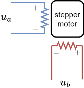
Bipolar stepper motors have two phases that are completely independent. Each of them has their own phase resistance.

They are typically driven with two independent full-bridge circuits. Full-bridge drivers allow both positive and negative voltages. 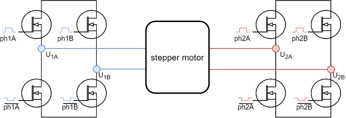
Having two full-bridge circuits requires four half-bridge drivers, which are often harder to source. BLDC drivers with three half-bridges are much more common. This raises the question: what happens if we connect two stepper wires together
and drive it with a BLDC driver?
Phase resistance imbalance
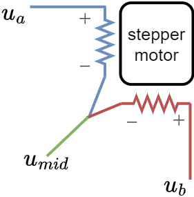
When phases connect at a midpoint, resistance becomes unbalanced:
Compared to a traditional BLDC motor driven by the same driver:
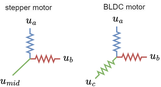
For winding resistance \(R\):
- \(u_a\) to \(u_{mid}\): \(R\)
- \(u_b\) to \(u_{mid}\): \(R\)
- \(u_a\) to \(u_b\): \(2R\)
This creates an unbalanced system. This relationship must be considered when calculating the voltage vector space and the maximum voltage that can be applied for a given supply voltage.
Voltage Vector Space
Traditional Stepper (Full Bridge)
A regular stepper motor, driven with two full bridges which can produce any phase voltage between \(-U_{max}\) and \(U_{max}\),
- \[u_a \in [-U_{max}, U_{max}]\]
- \[u_b \in [-U_{max}, U_{max}]\]
where \(U_{max}\) is usually the power supply voltage. Any phase voltage vector can be achieved by combining the \(u_a\) and \(u_b\) phases.
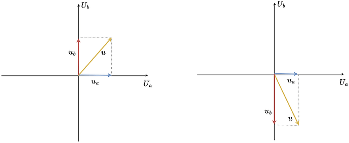
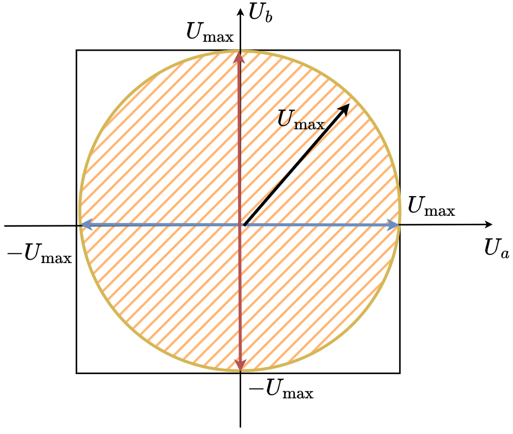
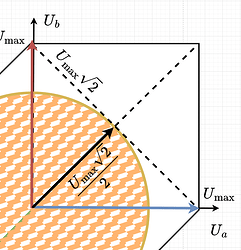
As both \(u_a\) and \(u_b\) are limited with \(U_{max}\), the set of all possible phase voltage vectors can be described by a square:
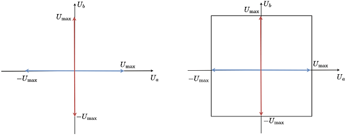
As in SimpleFOC we want to be able to guarantee that we can achieve any vector magnitude with any orientation in space (electrical angle) we limit the voltage vector magnitude to the \(U_{max}\) and we sacrifice some parts of the possible vectors.
Hybrid Stepper (3-Phase BLDC)
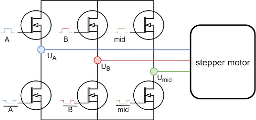
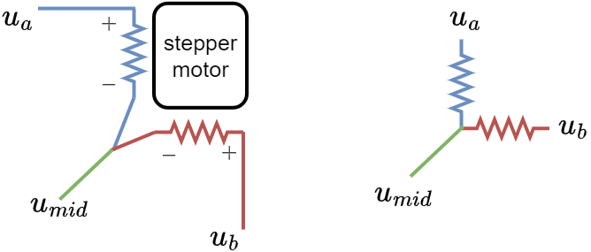
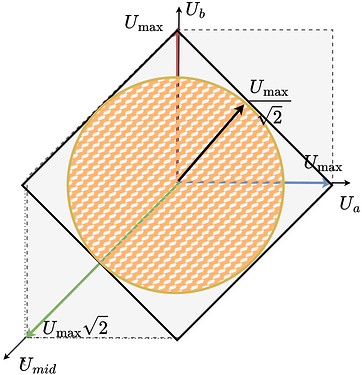
When two phases of a stepper are connected together, we obtain three unipolar (only positive) voltage vectors \(u_a\), \(u_b\) and \(u_{mid}\). These vectors can be visualized in space like this:

The vectors \(u_a\) and \(u_b\) are the same vectors as for a regular stepper but unipolar. They are 90 degrees apart. The vector \(u_{mid}\) is also unipolar and is 135 degrees from \(u_a\) and \(u_b\).
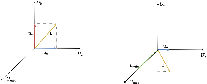
They can still create a rotating voltage vector and apply a voltage vector in any direction in space (any electric angle). However, in this configuration it can no longer cover the whole square as shown for regular stepper motors.
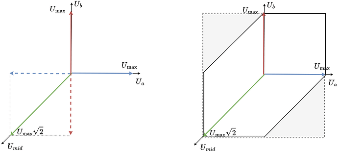
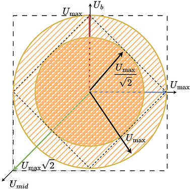
Instead of the square, the space of all the reachable voltage vectors is this elongated hexagon. To find the maximum voltage vector magnitude that can be generated in any direction in space (electrical angle), fit the largest possible circle in this hexagon.
If we imagine a line between \(u_a =U_{max}\) and \(u_b=U_{max}\), the circle will be touching it, as it touches the same line on the left side (line between \(u_a =-U_{max}\) and \(u_b=U_{max}\)).
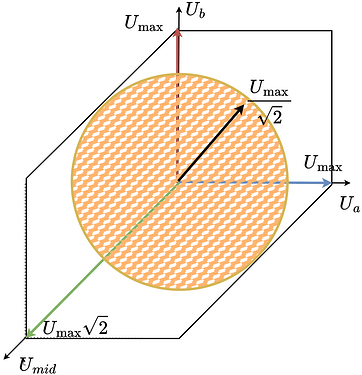
This line’s length is \(U_{max}\sqrt{2}\), the diagonal of a square with side length \(U_{max}\). Because the circle touches this line at the midpoint, the opposite diagonal from \(u_a=u_b=0\) to \(u_a=u_b=U_{max}\) has the same length and the circle touches it at the midpoint as well. Therefore the radius is \(U_{max}\sqrt{2}/2\), which simplifies to \(U_{max}/\sqrt{2}\).
So this new stepper configuration can be effectively seen as a stepper with the power supply voltage equal to the \(U_{max}/\sqrt{2}\).
Side-by-side comparison:
PWM modulation
Two modulation options are supported for this configuration:
- Sinusoidal modulation
- Space vector modulation
Sinusoidal modulation
The library computes the phase voltages from \(u_q\), \(u_d\) and electrical angle \(\theta_e\):
\[\begin{align} u_\alpha &= \cos(\theta_e)\,u_d - \sin(\theta_e)\,u_q \\ u_\beta &= \sin(\theta_e)\,u_d + \cos(\theta_e)\,u_q\\ u_{mid} &= \frac{U_{max}}{2} \end{align}\]Then the driver voltages can be calculated as:
\[\begin{align} u_a &= u_\alpha + u_{mid}\\ u_b &= u_\beta + u_{mid}\\ u_c &= u_{mid} \end{align}\]The library implements this in HybridStepperMotor::setPhaseVoltage().
void HybridStepperMotor::setPhaseVoltage(float Uq, float Ud, float angle_el)
{
  float center;
  float _sa, _ca;

  _sincos(angle_el, &_sa, &_ca);

  switch (foc_modulation) {
    ...
  case FOCModulationType::SinePWM:
    // C phase is fixed at half-rail to provide bias point for A, B legs
    Ua = (_ca * Ud) - (_sa * Uq);
    Ub = (_sa * Ud) + (_ca * Uq);

    center = driver->voltage_limit / 2;

    Ua += center;
    Ub += center;
    Uc = center;
    break;
    ...

  }
  driver->setPwm(Ua, Ub, Uc);

}
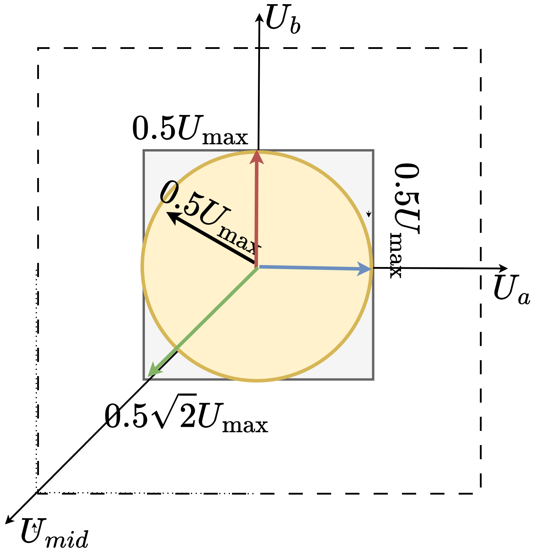
The limitation of this approach is that the maximum voltage vector magnitude is only half of the supply voltage, as the \(u_a\) and \(u_b\) can only be modulated around the fixed midpoint.
Space vector modulation
The library computes \(u_a\) and \(u_b\) exactly like in sine modulation, but moves the midpoint so the available voltage is maximized.
SimpleFOC implementation (SVPWM):
\[\begin{align} u_\alpha &= \cos(\theta_e)\,u_d - \sin(\theta_e)\,u_q \\ u_\beta &= \sin(\theta_e)\,u_d + \cos(\theta_e)\,u_q \end{align}\]Then the midpoint is shifted to keep \(u_a\) and \(u_b\) inside \([0, U_{max}]\) while maximizing amplitude:
\[\begin{align} U_{min} &= \min(u_\alpha, u_\beta, 0)\\ U_{max} &= \max(u_\alpha, u_\beta, 0)\\ u_{mid} &= -\frac{U_{min}+U_{max}}{2} + \frac{U_{max}}{2} \end{align}\]And the driver voltages are:
\[\begin{align} u_a &= u_\alpha + u_{mid}\\ u_b &= u_\beta + u_{mid}\\ u_c &= u_{mid} \end{align}\]The library implements this in HybridStepperMotor::setPhaseVoltage():
void HybridStepperMotor::setPhaseVoltage(float Uq, float Ud, float angle_el)
{
  float center;
  float _sa, _ca;

  _sincos(angle_el, &_sa, &_ca);

  switch (foc_modulation) {
    ...
  case FOCModulationType::SpaceVectorPWM:
    Ua = (_ca * Ud) - (_sa * Uq);
    Ub = (_sa * Ud) + (_ca * Uq);

    float Umin = fmin(fmin(Ua, Ub), 0);
    float Umax = fmax(fmax(Ua, Ub), 0);
    float Vo = -(Umin + Umax)/2 + driver->voltage_limit/2;

    Ua = Ua + Vo;
    Ub = Ub + Vo;
    Uc = Vo;
    break;
    ...

  }
  driver->setPwm(Ua, Ub, Uc);

}
This increases the maximum usable voltage vector from \(U_{max}/2\) (sine) to \(U_{max}/\sqrt{2}\).
Takeaway
SVPWM is the preferred option for hybrid steppers because it repositions the midpoint and preserves the largest possible voltage vector for all angles. This is why SimpleFOClibrary uses the dynamic midpoint in SpaceVectorPWM and why the recommended voltage limit is \(U_{max}/\sqrt{2}\) for BLDC drivers.
| Driver type | Modulation type | Max voltage vector magnitude |
|---|---|---|
| BLDC driver | Sinusoidal modulation | \(U_{max}/2\) |
| BLDC driver | Space vector modulation | \(U_{max} / \sqrt{2}\) |
| Stepper driver | Sinusoidal modulation | \(U_{max}\) |
The table above and the images show the clear trade-off: using a common 3-phase BLDC driver is cost-effective and works well with FOC, but the maximum voltage vector is reduced. In practice this means lower peak torque and top speed compared to a full-bridge stepper driver.
If you need to use this full current and voltage capability, you can either:
- Use a full bridge driver with 4 half-bridges (more expensive and less common)
- Use two separate BLDC drivers, one for each phase (more complex wiring but the control is the same as for a regular stepper)
- Use higher supply voltage to compensate for the reduced voltage vector magnitude (careful with this as it can damage the motor and driver if not done properly)
Related topics
- PWM Modulation Strategies
- Coordinate Transformations in FOC
- Torque Control Methods in FOC
- Current Sense align