On this page
Torque control implementation v2.4+
BLDC motors Stepper motors Hybrid Stepper motors
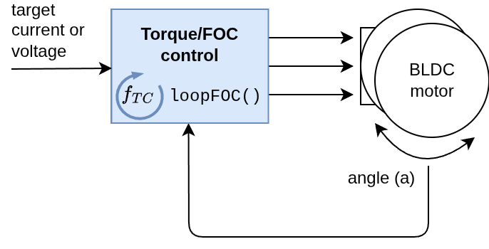
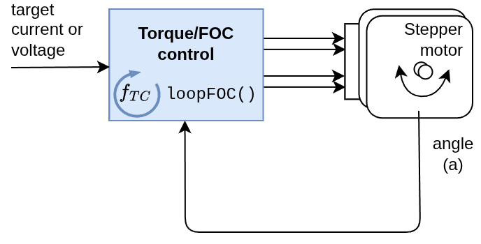
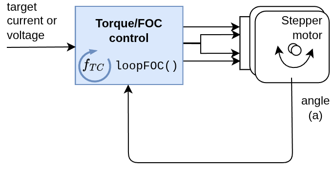
The SimpleFOClibrary implements 4 different torque control strategies, selected via the motor.torque_controller parameter. All torque control modes are executed within the loopFOC() function and convert the current setpoint (current_sp) into voltage commands (voltage.q and voltage.d) that are applied to the motor.
Torque Control Modes
// Torque control type
enum TorqueControlType : uint8_t {
  voltage            = 0x00,     // Torque control using voltage
  dc_current         = 0x01,     // Torque control using DC current
  foc_current        = 0x02,     // Torque control using dq currents
  estimated_current  = 0x03      // Torque control using estimated current
};
The torque control mode is selected by setting:
motor.torque_controller = TorqueControlType::voltage; // or dc_current, foc_current, estimated_current
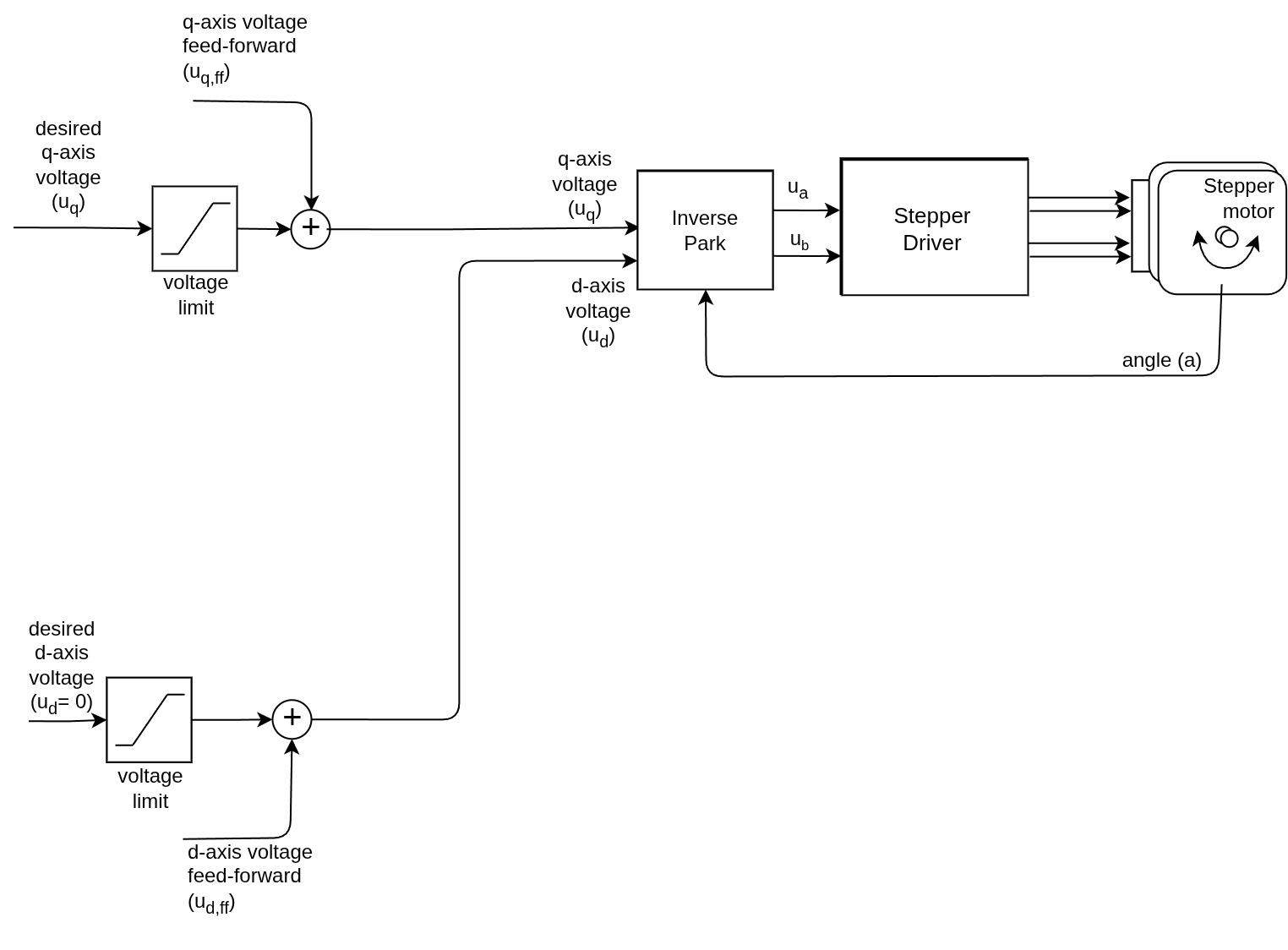
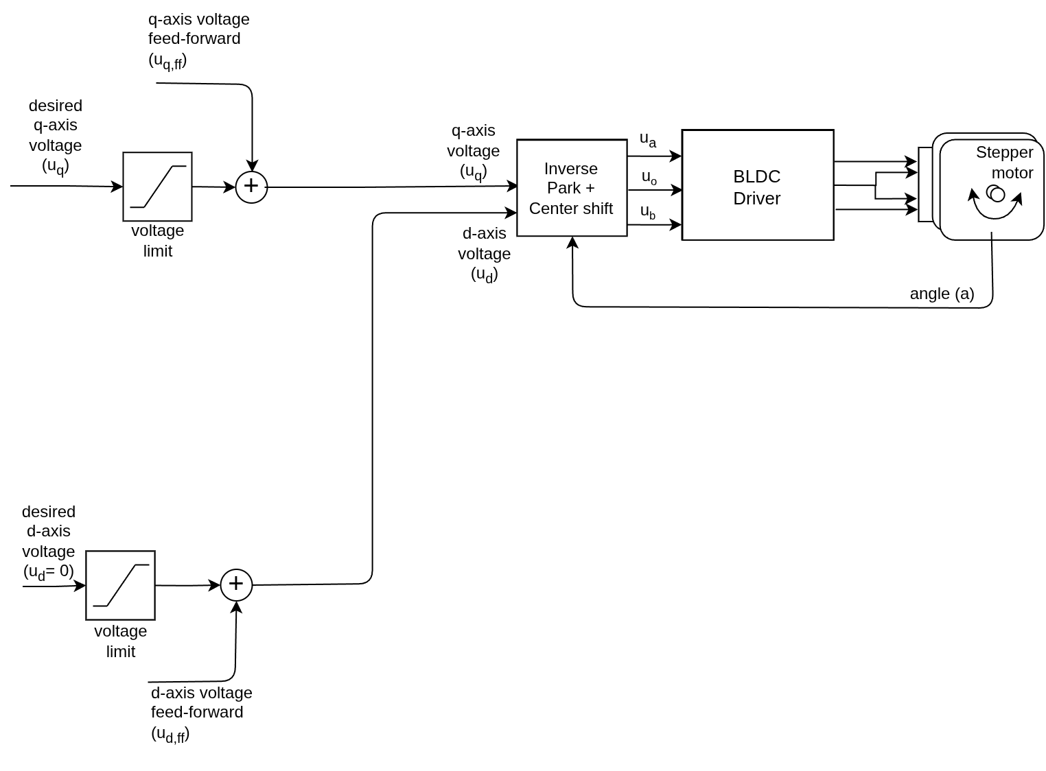
Voltage Mode
Type: TorqueControlType::voltage
The simplest torque control method, suitable when current sensing is not available. It assumes that voltage is proportional to current, which is proportional to torque.
BLDC motors Stepper motors Hybrid Stepper motors
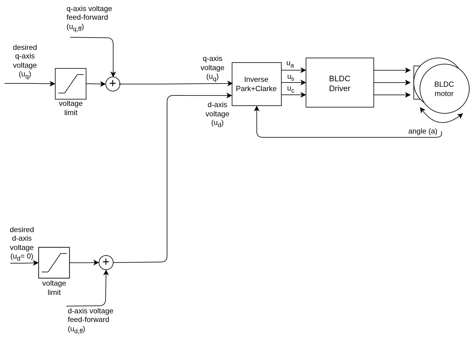
Implementation
From FOCMotor::loopFOC():
case TorqueControlType::voltage:
  voltage.q = _constrain(current_sp, -voltage_limit, voltage_limit) + feed_forward_voltage.q;
  voltage.d = feed_forward_voltage.d;
  break;
Configuration
motor.torque_controller = TorqueControlType::voltage;
motor.voltage_limit = 12.0;  // Maximum voltage [V]
motor.feed_forward_voltage.q = 0.0;  // Optional feed-forward
motor.feed_forward_voltage.d = 0.0;
See the voltage control API documentation See a deeper dive in voltage control theory
Estimated Current Mode
Type: TorqueControlType::estimated_current
BLDC motors Stepper motors Hybrid Stepper motors
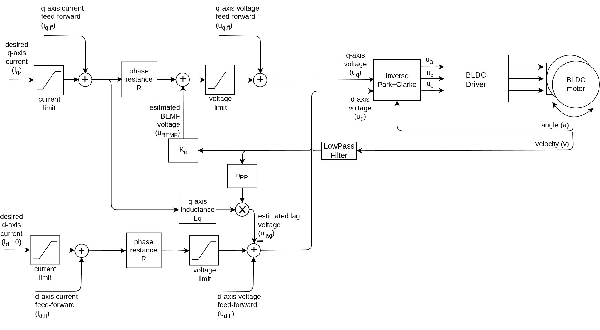

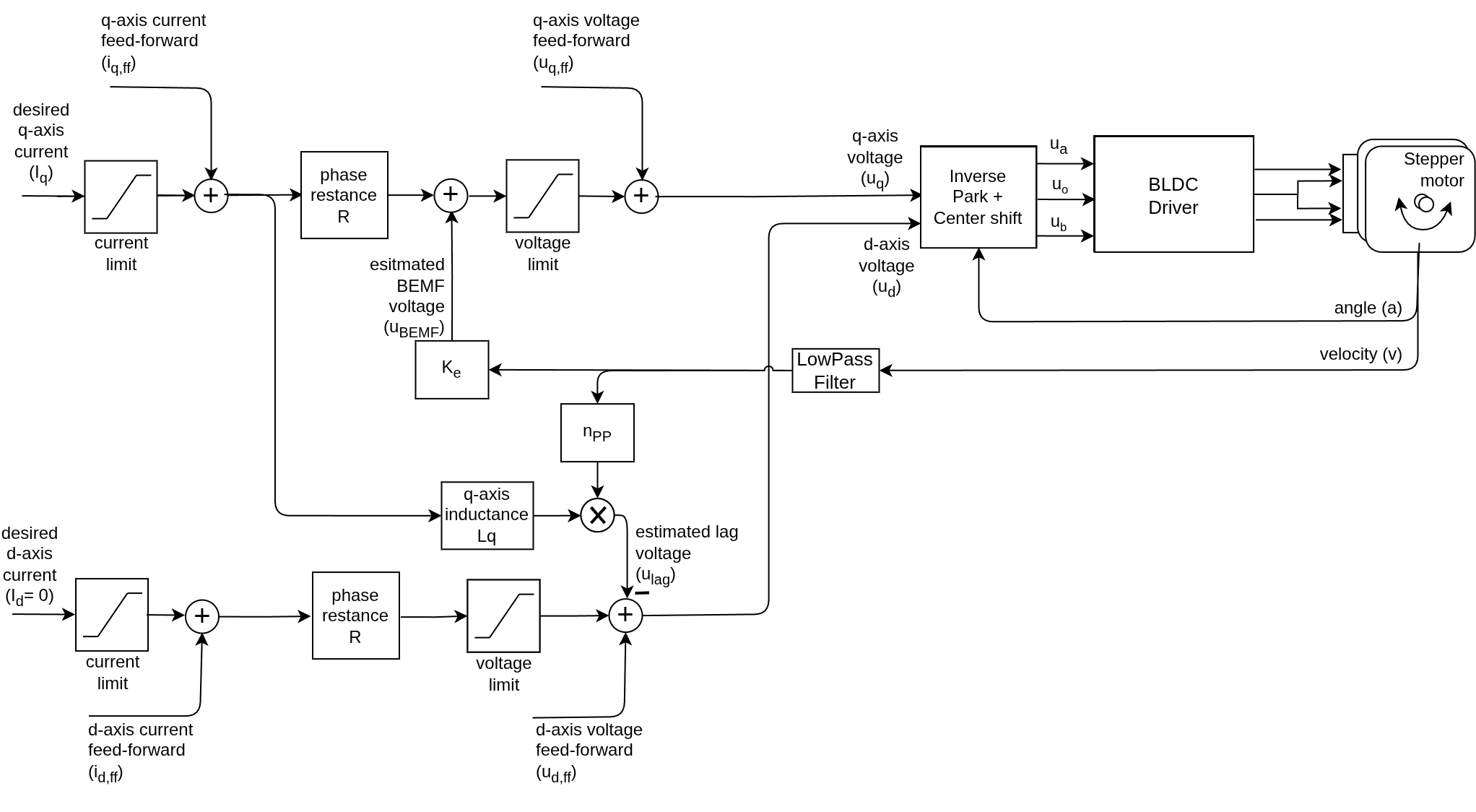
Estimates the current based on motor parameters (phase resistance and KV rating) without requiring a current sensor. Provides better torque control than voltage mode but requires accurate motor parameters.
Implementation
From FOCMotor::loopFOC():
case TorqueControlType::estimated_current:
  if(!_isset(phase_resistance)) return;
  // constrain current setpoint
  current_sp = _constrain(current_sp, -current_limit, current_limit) + feed_forward_current.q;
  // calculate the back-emf voltage if KV_rating available
  if (_isset(KV_rating)) voltage_bemf = estimateBEMF(shaft_velocity);
  // filter the current estimate
  current.q = LPF_current_q(current_sp);
  // calculate the phase voltage: V = I*R + V_bemf
  voltage.q = current.q * phase_resistance + voltage_bemf;
  // constrain voltage
  voltage.q = _constrain(voltage.q, -voltage_limit, voltage_limit) + feed_forward_voltage.q;
  // d voltage - lag compensation
  if(_isset(axis_inductance.q))
    voltage.d = _constrain(-current_sp*shaft_velocity*pole_pairs*axis_inductance.q,
                           -voltage_limit, voltage_limit) + feed_forward_voltage.d;
  else voltage.d = feed_forward_voltage.d;
  break;
Motor Model
The voltage calculation is based on the motor electrical model:
\[u_q = R \cdot i_q + K_e \cdot \omega\]Where:
- \(u_q\) : Phase voltage
- \(i_q \cdot R\) : Resistive voltage drop
- \(K_e \cdot \omega = u_{BEMF}\) : Back-EMF voltage (calculated from velocity and KV rating)
Additionally the inductive voltage drop can be compensated if the motor inductance is known:
\[u_d = -L_q \cdot i_q \cdot \omega\]Configuration
motor.torque_controller = TorqueControlType::estimated_current;
motor.current_limit = 5.0;      // Maximum current [A]
motor.voltage_limit = 12.0;     // Maximum voltage [V]

// Required motor parameters
motor.phase_resistance = 2.5;   // Phase resistance [Ohm]
motor.KV_rating = 100;          // Motor KV rating [rpm/V] or provide via motor constructor

// Low pass filter velocity for BEMF compensation
motor.LPF_velocity.Tf = 0.01;  // 10ms time constant

// Optional: lag compensation
motor.axis_inductance.q = 0.00015;  // [H]

// Optional: feed-forward
motor.feed_forward_voltage.q = 0.0;
motor.feed_forward_voltage.d = 0.0;
Motor Parameter Identification
To use this mode effectively, you need to know your motor parameters. The library provides a helper function that uses current sensing to measure the motor’s phase resistance and inductance, which can then be used for better estimation even without current sensing in normal operation.
// In setup(), after motor.init() and motor.initFOC():
motor.characteriseMotor(voltage_test);  // Measures R, L
See a deeper dive in estimated current control theory See the estimated current control API documentation Low-pass filter implementation
DC Current Mode
Type: TorqueControlType::dc_current
BLDC motors Stepper motors Hybrid Stepper motors
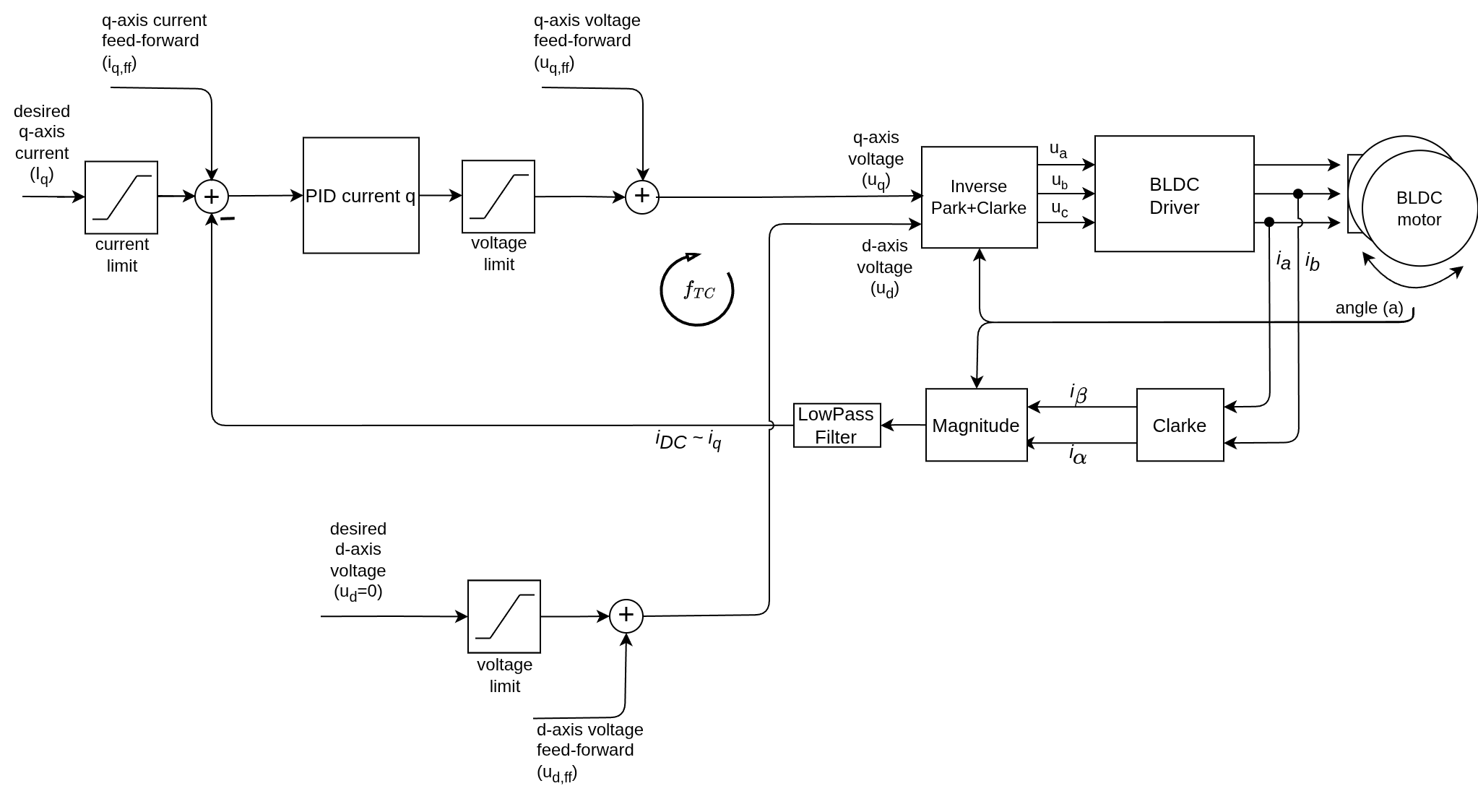
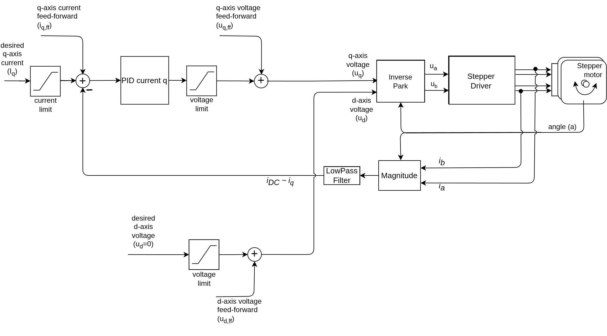
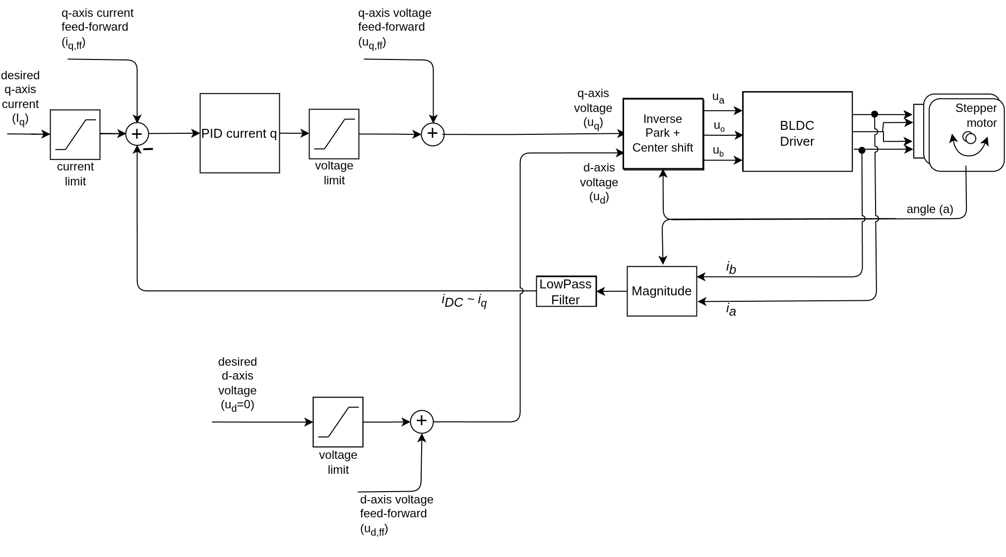
Uses current sensing to measure the overall current magnitude and regulates it with a PID controller. Requires a current sensor but only measures total current, not individual phase currents.
Implementation
From FOCMotor::loopFOC():
case TorqueControlType::dc_current:
  if(!current_sense) return;
  // constrain current setpoint
  current_sp = _constrain(current_sp, -current_limit, current_limit) + feed_forward_current.q;
  // read overall current magnitude
  current.q = current_sense->getDCCurrent(electrical_angle);
  // filter the value
  current.q = LPF_current_q(current.q);
  // calculate the phase voltage using PID
  voltage.q = PID_current_q(current_sp - current.q) + feed_forward_voltage.q;
  // d voltage - lag compensation
  if(_isset(axis_inductance.q))
    voltage.d = _constrain(-current_sp*shaft_velocity*pole_pairs*axis_inductance.q,
                           -voltage_limit, voltage_limit) + feed_forward_voltage.d;
  else voltage.d = feed_forward_voltage.d;
  break;
Configuration
motor.torque_controller = TorqueControlType::dc_current;
motor.current_limit = 5.0;  // Maximum current [A]
motor.voltage_limit = 12.0;

// PID controller for current loop
motor.PID_current_q.P = 5.0;
motor.PID_current_q.I = 300.0;
motor.PID_current_q.D = 0.0;
motor.PID_current_q.output_ramp = 1e6;
motor.PID_current_q.limit = motor.voltage_limit;

// Low pass filter for current measurement
motor.LPF_current_q.Tf = 0.005;  // 5ms time constant

// Optional: lag compensation (requires motor parameter)
motor.axis_inductance.q = 0.00015;  // [H]
Advanced Features
Lag Compensation: Compensates for the phase lag introduced by motor inductance at high speeds, based on the motor model: \(u_d = -L_q \cdot \frac{di_q}{dt} \approx -L_q \cdot i_q \cdot \omega\)
Or in code:
voltage.d -= current_sp * shaft_velocity * pole_pairs * axis_inductance.q;
See the DC current control API documentation PID controller implementation Low-pass filter implementation
FOC Current Mode
Type: TorqueControlType::foc_current
BLDC motors Stepper motors Hybrid Stepper motors
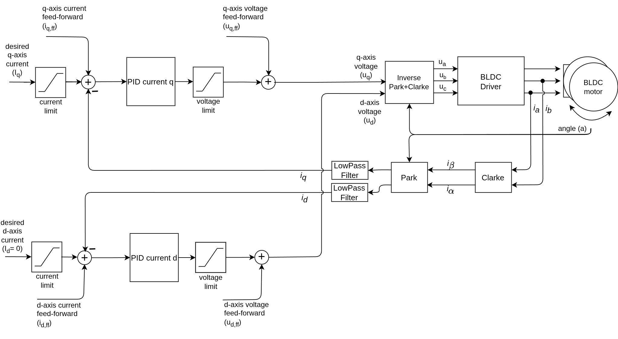
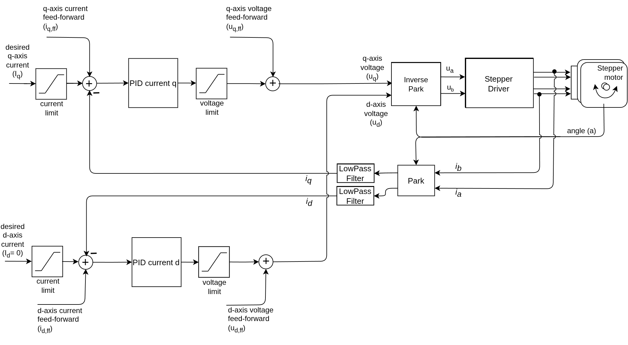
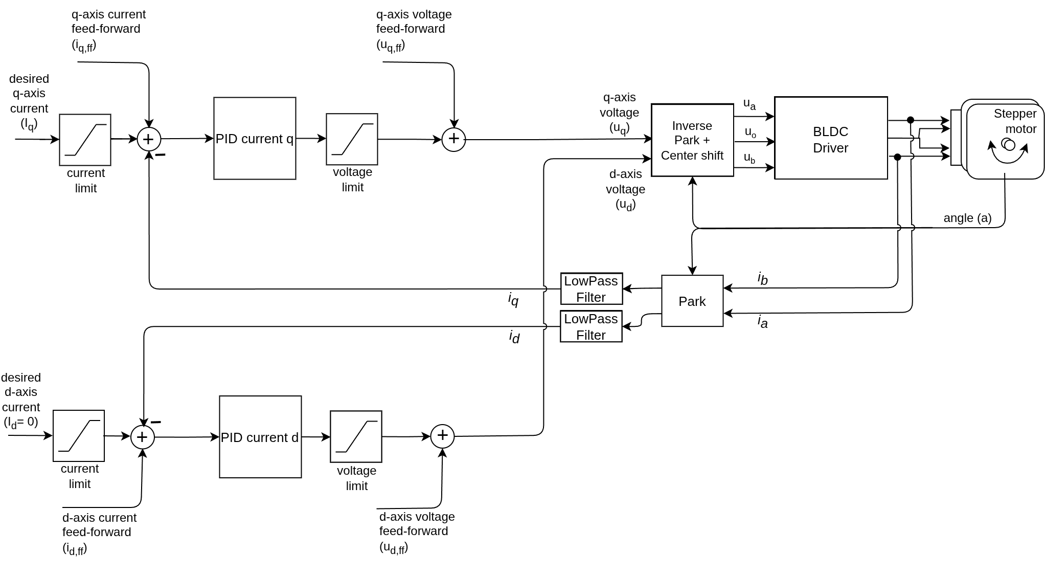
The most accurate torque control method. Measures and controls both d and q axis currents independently using two PID controllers. This is true Field Oriented Control with full current feedback.
Implementation
From FOCMotor::loopFOC():
case TorqueControlType::foc_current:
  if(!current_sense) return;
  // constrain current setpoint
  current_sp = _constrain(current_sp, -current_limit, current_limit) + feed_forward_current.q;
  // read dq currents
  current = current_sense->getFOCCurrents(electrical_angle);
  // filter values
  current.q = LPF_current_q(current.q);
  current.d = LPF_current_d(current.d);
  // calculate the phase voltages using two PIDs
  voltage.q = PID_current_q(current_sp - current.q);
  voltage.d = PID_current_d(feed_forward_current.d - current.d);
  // lag compensation
  if(_isset(axis_inductance.q))
    voltage.d = _constrain(voltage.d - current_sp*shaft_velocity*pole_pairs*axis_inductance.q,
                           -voltage_limit, voltage_limit);
  // cross coupling compensation
  if(_isset(axis_inductance.d))
    voltage.q = _constrain(voltage.q + current.d*shaft_velocity*pole_pairs*axis_inductance.d,
                           -voltage_limit, voltage_limit);
  // add feed forward
  voltage.q += feed_forward_voltage.q;
  voltage.d += feed_forward_voltage.d;
  break;
Configuration
motor.torque_controller = TorqueControlType::foc_current;
motor.current_limit = 5.0;  // Maximum current [A]
motor.voltage_limit = 12.0;

// Q-axis PID controller (torque-producing current)
motor.PID_current_q.P = 5.0;
motor.PID_current_q.I = 300.0;
motor.PID_current_q.D = 0.0;
motor.PID_current_q.output_ramp = 1e6;
motor.PID_current_q.limit = motor.voltage_limit;

// D-axis PID controller (flux-producing current)
motor.PID_current_d.P = 5.0;
motor.PID_current_d.I = 300.0;
motor.PID_current_d.D = 0.0;
motor.PID_current_d.output_ramp = 1e6;
motor.PID_current_d.limit = motor.voltage_limit;

// Low pass filters
motor.LPF_current_q.Tf = 0.005;  // 5ms
motor.LPF_current_d.Tf = 0.005;  // 5ms

// Optional: motor inductances for compensation
motor.axis_inductance.q = 0.00015;  // [H]
motor.axis_inductance.d = 0.00015;  // [H]

// Optional: feed-forward
motor.feed_forward_current.d = 0.0;  // Usually 0 for surface-mount motors
motor.feed_forward_voltage.q = 0.0;
motor.feed_forward_voltage.d = 0.0;
PID controller implementation Low-pass filter implementation
Advanced Features
Lag Compensation:
Based on the motor electrical model, the inductive voltage drop can be compensated to improve high-speed performance:
\[u_d = -L_q \cdot \frac{di_q}{dt} \approx -L_q \cdot i_q \cdot \omega\]Compensates for the phase lag introduced by motor inductance at high speeds:
voltage.d -= current_sp * shaft_velocity * pole_pairs * axis_inductance.q;
Cross-Coupling Compensation:
Based on the motor model, the interaction between d and q axes can be compensated to improve accuracy:
\[u_q = R \cdot i_q + K_e \cdot \omega + L_d\frac{di_d}{dt} \approx R \cdot i_q + K_e \cdot \omega + L_d \cdot i_d \cdot \omega\]Compensates for the interaction between d and q axes:
voltage.q += current.d * shaft_velocity * pole_pairs * axis_inductance.d;
See the FOC algorithm theory documentation
Quick Selection Guide
Choose Voltage Mode if:
- No current sensing available
- Low-power applications (gimbal motors)
- Cost is primary concern
- Basic control is sufficient
Choose DC Current Mode if:
- Single shunt or DC link sensing available
- Need current limiting
- Cost-sensitive but need better accuracy than voltage
Choose FOC Current Mode if:
- Highest performance required
- Current sensing hardware available
- Applications requiring precise torque control
- High-speed operation with field weakening
Choose Estimated Current Mode if:
- No current sensing available
- Motor parameters are well known
- Need current limiting without hardware
- Better accuracy than voltage mode required
See more info in the torque control API documentation
Implementation in loopFOC()
All torque control modes are executed in the loopFOC() function. Here’s the overall flow:
void FOCMotor::loopFOC() {
  // Update sensor
  if (sensor) sensor->update();

  // If disabled or not ready, return
  if(!enabled || motor_status != FOCMotorStatus::motor_ready) return;

  // Calculate electrical angle
  electrical_angle = electricalAngle();

  // Execute torque control based on selected mode
  switch (torque_controller) {
    case TorqueControlType::voltage:
      // Direct voltage control
      break;
    case TorqueControlType::dc_current:
      // DC current control with PID
      break;
    case TorqueControlType::foc_current:
      // Full FOC with d/q current control
      break;
    case TorqueControlType::estimated_current:
      // Model-based current estimation
      break;
  }

  // Apply calculated voltages to motor phases
  setPhaseVoltage(voltage.q, voltage.d, electrical_angle);
}
The setPhaseVoltage() function then uses the FOC algorithm to convert d/q voltages into three-phase voltages (or two-phase for stepper motors) and applies them via PWM.
See the FOC algorithm implementation docs
Related Documentation
Motion Control Implementation PID Implementation Low-Pass Filter Implementation