On this page
Connecting the hardware to SimpleFOC-microspora
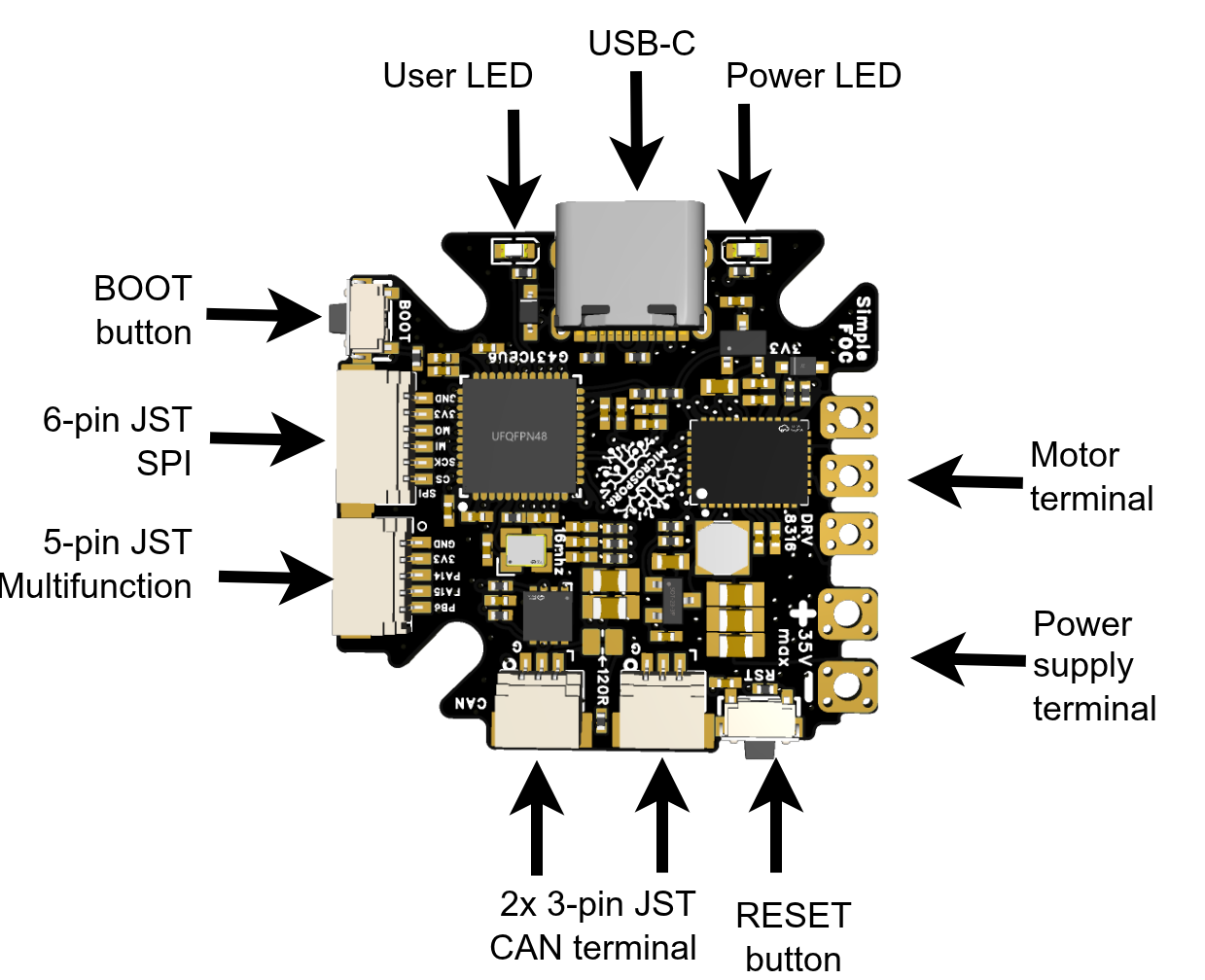
SimpleFOC-microspora is an all-in-one motor controller. It combines an STM32G431CBU6 microcontroller, a DRV8316 6-PWM motor driver, an MT6701 magnetic encoder, current sensing, voltage sensing, USB-C, CAN, SPI, and a multifunction 5-pin header.
Motor connection
The board supports both BLDC motors and stepper motors through the hybris stepper mode.
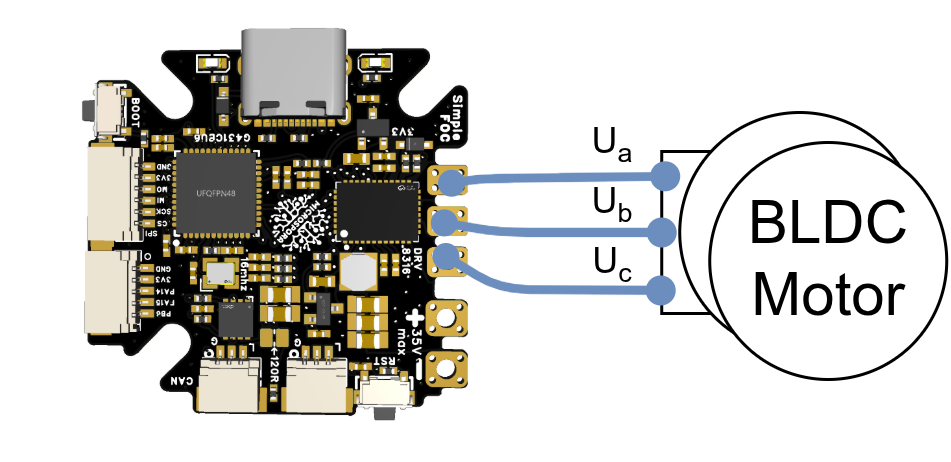
Using BLDC motors is easy with this board, simply connect the three motor phases to the corresponding outputs.
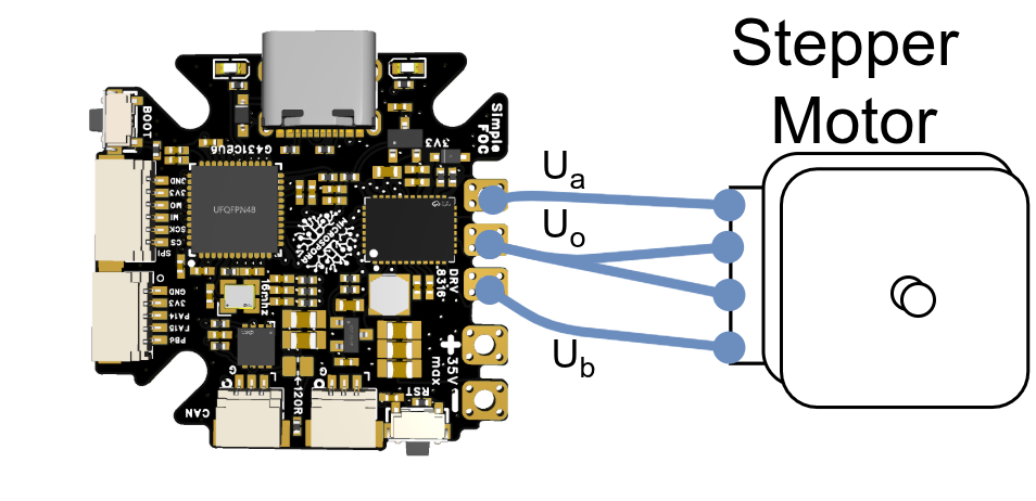
For steppers, first identify the phases A and B of the motor. Then connect the A+ and B+ to the outside motor terminals, while the A- and B- are connected together to the inside motor terminal.
Read a deeper dive in Hybrid Stepper mode
Motor phase resistance considerations.
This driver is not suitable for very low resistance BLDC motors, typically those below 0.1Ω. The RDS(on) of the DRV8316 MOSFETs can is around 100mΩ which is comparable to the high-power BLDC motors and can cause significant heating and power loss. This driver's max current is around 8A, so take this in consideration when selecting motors and operating conditions.
Power supply
The board allows a range of power-supply voltage from 8-35V DC. The DRV8316 provides an onboard 5V buck output for the board and supported peripherals. But the maximal current it can supply is limited to around 200mA. Which is typically sufficient for sensors and low-power peripherals. Only 3.3V output is available for peripherals using the JST connectors.
CAN connection
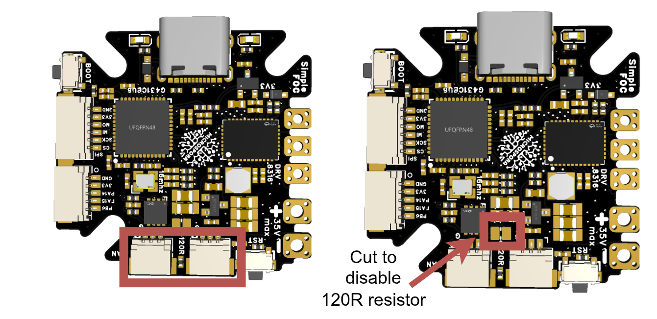
The board has two 3-pin JST connectors for CAN daisy chaining. They are electrically connected so additional Microspora boards can be connected in a chain.
| Pin | Signal |
|---|---|
| 1 | GND |
| 2 | CAN_H |
| 3 | CAN_L |
Use a 120Ω termination resistor at the physical ends of the CAN network. To disable the termination resistor, use a sharp exact o knife to cut the trace connecting the resistor. You can always re-enable it by soldering the solder pad back together.
The firmware examples use a 1Mbps CAN bus and include Python scripts for scanning the bus and sending motor commands. See the CAN scripts.
The CAN transceiver uses the following MCU signals:
| Signal | Pin | Description |
|---|---|---|
| CAN_RX | PB8 | CAN receive |
| CAN_TX | PB9 | CAN transmit |
| CAN_ENABLE | PC13 | CAN transceiver enable |
6-pin SPI header
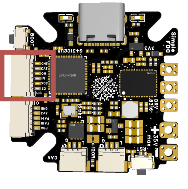
The 6-pin JST header exposes SPI3. This bus is shared with the DRV8316 driver, so configure the driver before using the header for another SPI device.
| Pin | Signal | Function |
|---|---|---|
| 1 | GND | Ground |
| 2 | PB5 | MOSI |
| 3 | PB4 | MISO |
| 4 | PC10 | SCK |
| 5 | PC11 | CS |
| 6 | 3.3V | 3.3V output |
5-pin multifunction header
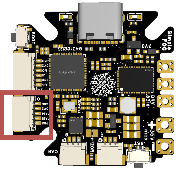
The 5-pin JST header can be used for I2C, UART, an external encoder, PWM, step/dir, or general-purpose I/O. It is compatible with many Qwiic and STEMMA QT cables; when using a 4-pin cable, leave the fifth signal unconnected as appropriate for the selected function.
| Pin | Signal | I2C | UART | Encoder / timer | PWM | Step/dir |
|---|---|---|---|---|---|---|
| 1 | GND | - | - | - | - | - |
| 2 | 3.3V | - | - | - | - | - |
| 3 | PA14 | SDA (I2C1) | RX (UART2) | TIM8_CH2 | PWM input (TIM8_CH2) | Direction (PA14) |
| 4 | PA15 | SCL (I2C1) | TX (UART2) | TIM8_CH1 | PWM input (TIM8_CH1) | Direction (PA15) |
| 5 | PB6 | - | - | TIM8_ETR | Direction (PB6) | Step input (TIM8_ETR) |
LEDs
The board has the following LEDs:
- Power LED: indicates the power-supply is connected.
- User LED: A LED on PC6, can be controlled by the user.
But you can also add many more using auxiliary JST connectors, especially if using STEMMA QT or Qwiic compatible devices.
Mounting the board
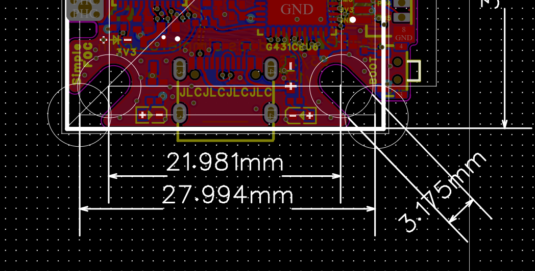
The board can be mounted using the three mounting slots that are made to accept M2 and M3 screws. They allow the board to be securely attached to a surface or enclosure of many common motors. And if the hole distances do not match your motor, a simple 3d printed adapter can be used to align the mounting holes properly.
The minimal hole distance is 22mm (corresponding to the holes of GM2804 and GM5208 motors), and the maximal hole distance is 28mm (corresponding to the holes of GM4108 motors).
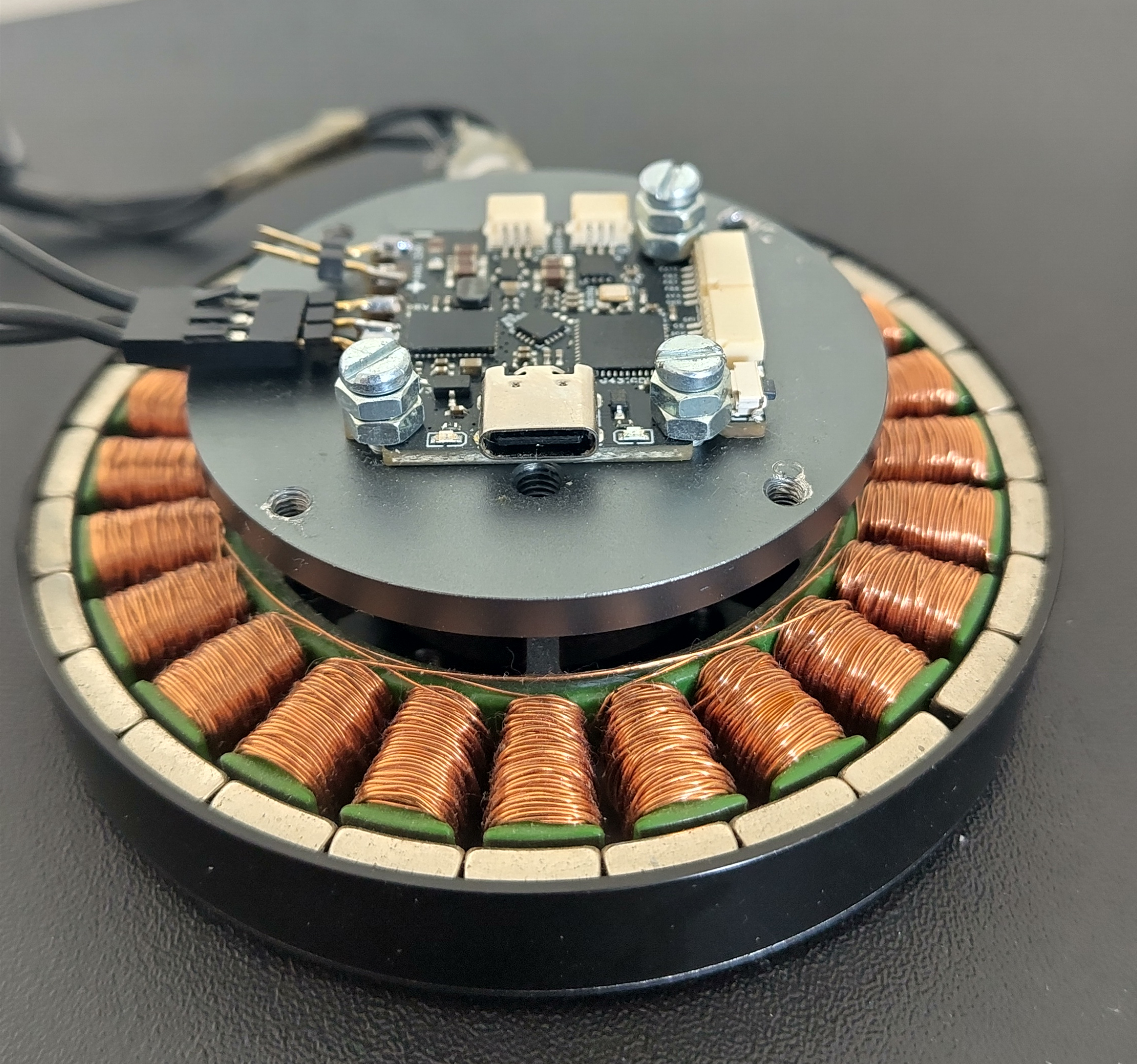
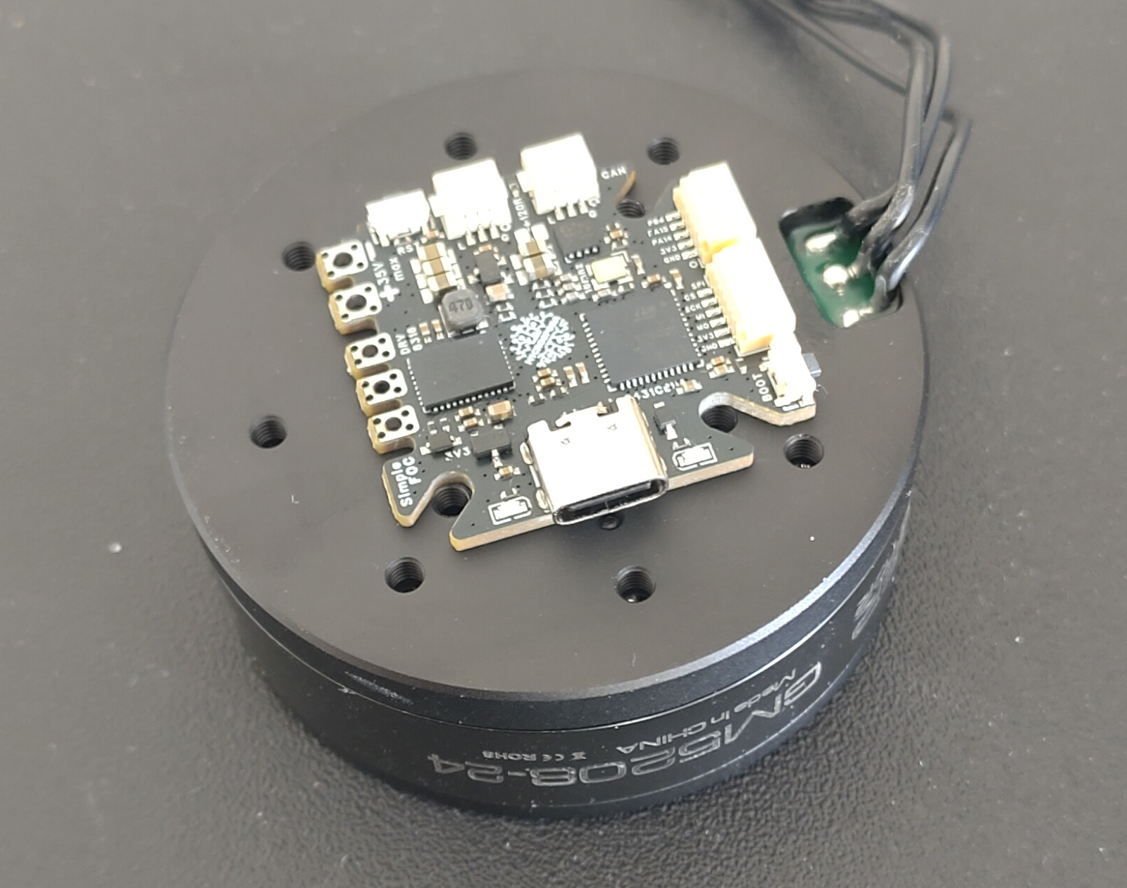
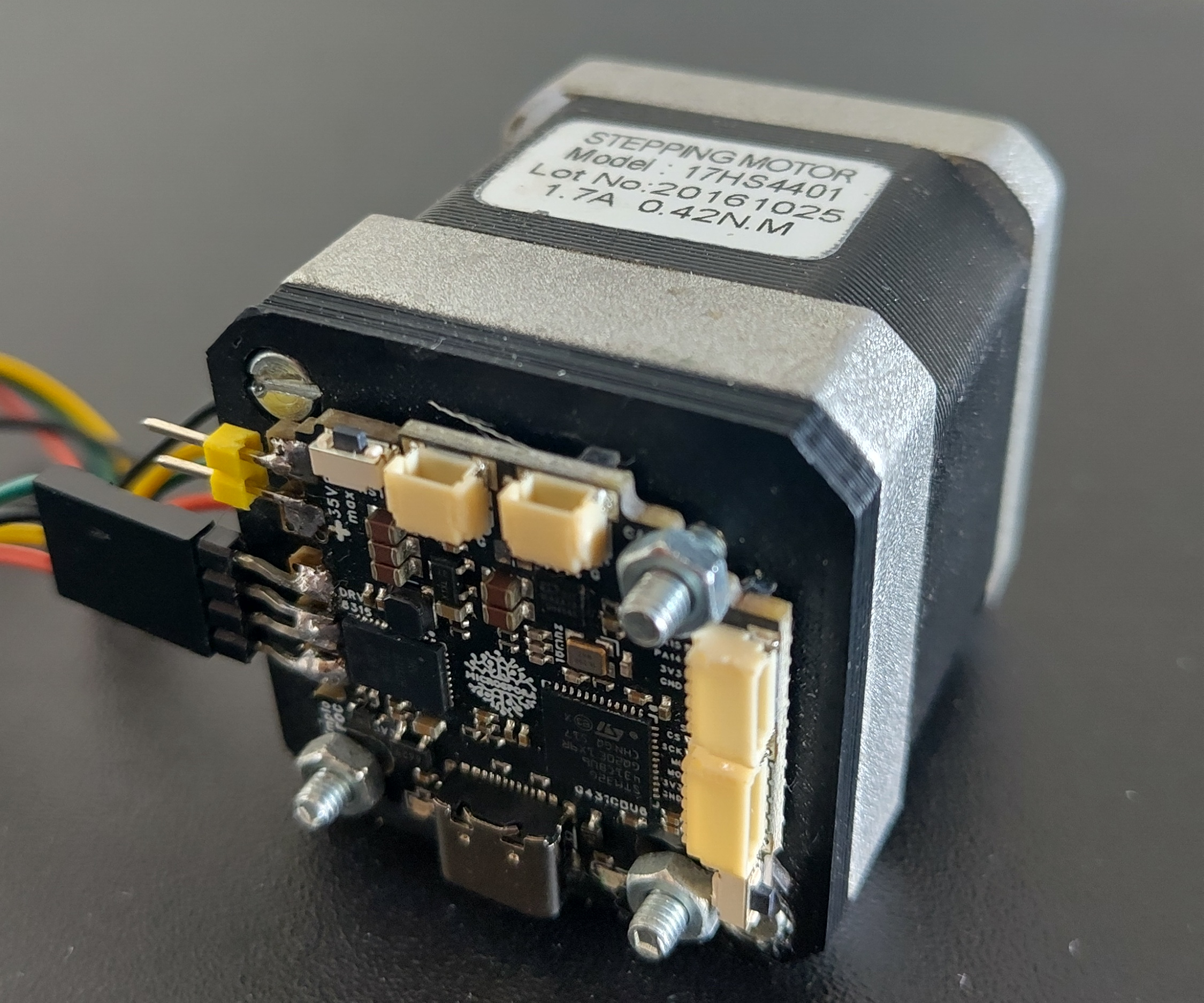
You can find a 3d model of the board in the github repository here.
Programming the board in DFU mode
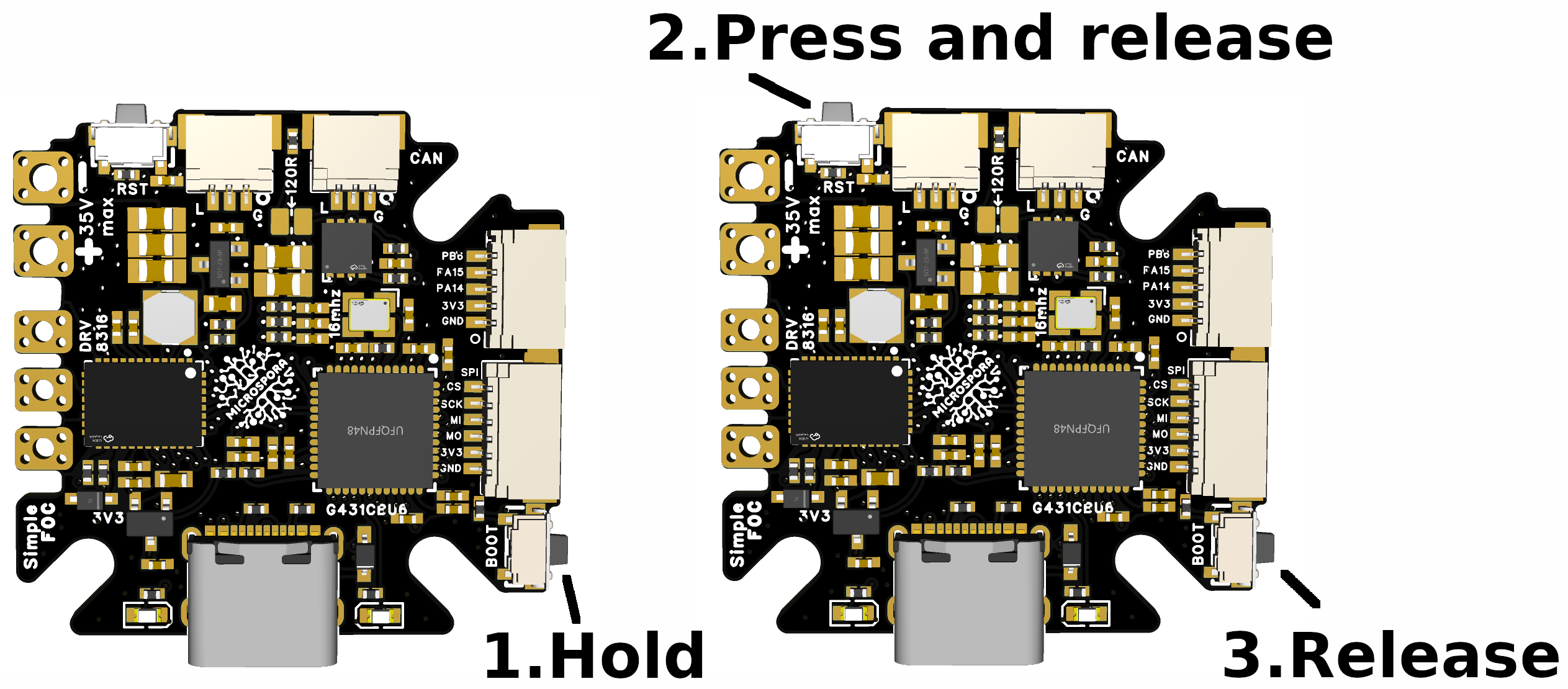
The board firmware can be built with PlatformIO and or Arduino IDE. But in order to flash the firmware the board needs to be in the DFU mode. To do so follow these steps:
- Connect the board to the computer using USB-C.
- Enter DFU mode: hold BOOT, press and release RESET, wait one or two seconds, then release BOOT.
- Upload the firmware from PlatformIO.
An example firmware for the Microspora board can be found in the Microspora firmware repository. The reference firmware runs the FOC loop from a 10kHz hardware-timer interrupt. Serial monitoring uses 250000 baud. The board also exposes the SimpleFOC Commander interface and optional SimpleFOC CAN communication.
Write your own firmware for the Microspora board