On this page
Microspora pinout reference
The board exposes the main motor, sensing, communication, and power-monitoring signals in a compact pin map suitable for SimpleFOC firmware configuration.
Motor driver and sensing
| Signal | Pin | Description |
|---|---|---|
| PHA_H | PA10 | High-side PWM for phase A |
| PHA_L | PB15 | Low-side PWM for phase A |
| PHB_H | PA9 | High-side PWM for phase B |
| PHB_L | PB14 | Low-side PWM for phase B |
| PHC_H | PA8 | High-side PWM for phase C |
| PHC_L | PB13 | Low-side PWM for phase C |
| ISENS_A | PA0 | Phase A current sense |
| ISENS_B | PA1 | Phase B current sense |
| ISENS_C | PA2 | Phase C current sense |
| VSENS | PB11 | Supply voltage sense input Voltage divider scaling factor is 11.0 (4.7k / 47k) |
Driver SPI interface
| Signal | Pin | Description |
|---|---|---|
| DRV_MOSI | PB5_ALT1 | DRV8316 SPI MOSI |
| DRV_MISO | PB4_ALT1 | DRV8316 SPI MISO |
| DRV_SCK | PC10 | DRV8316 SPI clock |
| DRV_CS | PC4 | DRV8316 SPI chip select |
MT6701 magnetic encoder
| Signal | Pin | Description |
|---|---|---|
| ENC_SDO | PA6 | Encoder SPI MISO |
| ENC_NC | PA7 | Not connected (dummy MOSI) |
| ENC_CLK | PA5 | Encoder clock |
| ENC_CS | PA4 | Encoder chip select |
CAN transceiver
| Signal | Pin | Description |
|---|---|---|
| CAN_RX | PB8 | CAN receive |
| CAN_TX | PB9 | CAN transmit |
| CAN_ENABLE | PC13 | CAN transceiver enable |
LEDs and Buttons
| Signal | Pin | Description |
|---|---|---|
| LED | PC6 | User LED |
| BOOT | PB8 | Boot button (can be used in user applications, but not at the same time as CAN) |
| RESET | - | Reset button |
| PWR | - | Power indicator LED |
Connectors
CAN connector
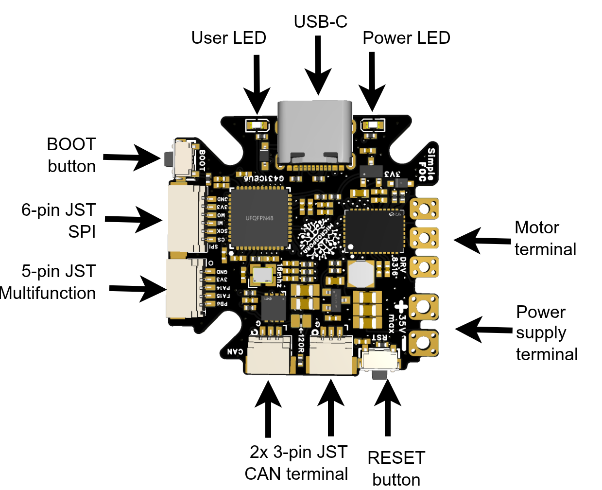
The board has a double 3-pin JST connector for daisy-chaining multiple boards using CAN. The order of pins is
| Number | Pin |
|---|---|
| 1 | GND |
| 2 | CAN_H |
| 3 | CAN_L |
SPI connector
The board has an additional 6-pin JST connector for SPI, with the following pinout:
| Number | Pin | Function |
|---|---|---|
| 1 | GND | GND |
| 2 | 3.3V | 3.3V |
| 3 | PB5 | MISO |
| 4 | PB4 | MOSI |
| 5 | PC10 | SCK |
| 6 | PC11 | CS |
This SPI header allows you to connect additional SPI devices to the board, such as an additional output shaft sensor or other SPI peripherals.
Note: This SPI bus is the same one used for the DRV8316 driver, so make sure to configure the driver before you use the SPI bus for other purposes.
I2C / Encoder / GPIO connector / Step/Dir
Finally, the board has a 5-pin JST connector for I2C, encoder, and GPIO. The pinout is as follows:
| Number | Signal | I2C | UART | Encoder / timer | PWM | Step/dir |
|---|---|---|---|---|---|---|
| 1 | GND | - | - | - | - | - |
| 2 | 3.3V | - | - | - | - | - |
| 3 | PA14 | SDA (I2C1) | RX (UART2) | TIM8_CH2 | PWM input (TIM8_CH2) | Direction (PA14) |
| 4 | PA15 | SCL (I2C1) | TX (UART2) | TIM8_CH1 | PWM input (TIM8_CH1) | Direction (PA15) |
| 5 | PB6 | - | - | TIM8_ETR | Direction (PB6) | Step input (TIM8_ETR) |
So this connector can be used for I2C, encoder, or GPIO depending on your application. Qwiic / Stemma-style cables can be used to connect to this connector, even though it is 5-pin instead of the usual 4-pin. For most cases teh 4-pin stemma cable will work fine.