On this page
Connecting the hardware to SimpleFOCMini v2.3
Connecting the SimpleFOCMini v2.3 to the microcontroller, BLDC motor and power-supply is very straight forward.
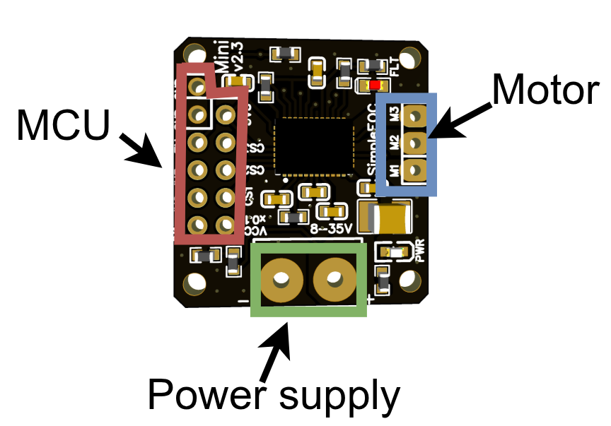
Connecting the motor
The mini board can be connected to either a BLDC motor or a stepper motor, depending on your application.
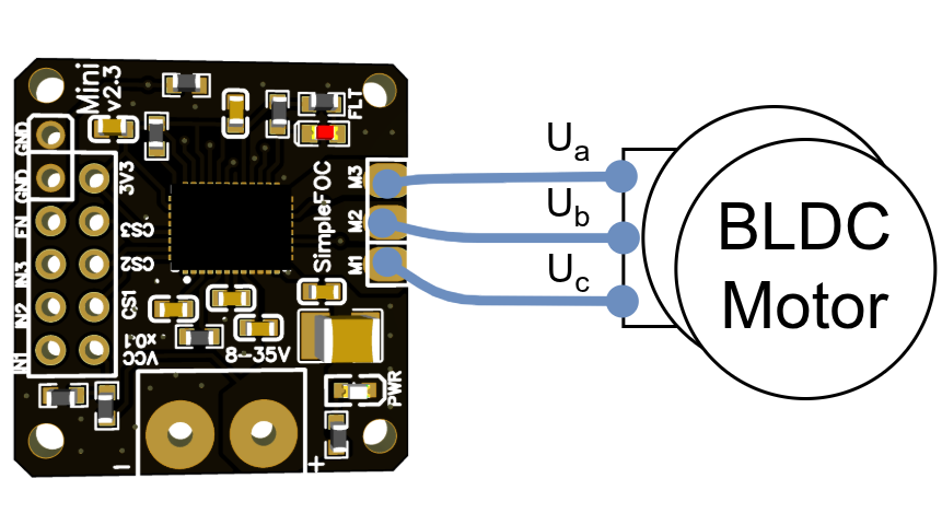
BLDC motor phases a, b and c are connected directly the motor terminal connector M1,M2 and M3
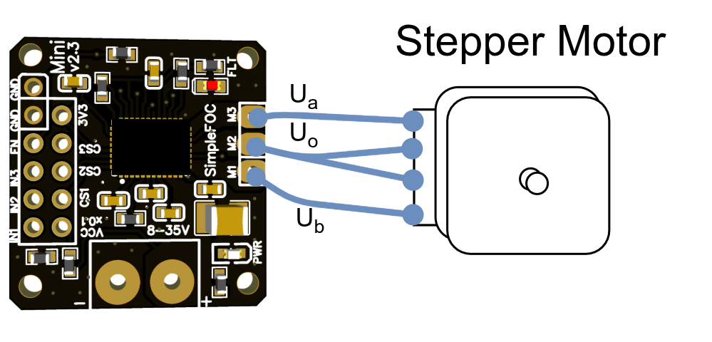
Stepper motor phases A+ and B+ need to be connected to the motor terminal connector M1 and M3, with M2 being used as the common coil (A- and B- at the same time).
BEWARE: Power limitations
SimpleFOCMini is designed for lower-power motors with internal resistance higher than R>1 Ohm. The absolute maximal current of this board is 8A. Please make sure when using this board in your projects that the motor used does comply with these limits.
If you still want to use this driver with the motors with very low resistance R < 1 Ohm make sure to limit the voltage set to the board.
For a bit more information about the choice of motors visit Motor docs
Microcontroller connection
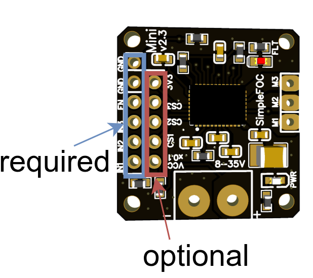
SimpleFOCMini v2.3 is designed as a standalone BLDC driver, which will basically work with any microcontroller. This board has 11 pins in two rows exposed for the connection to the microcontroller
The first row of pins contains the power and PWM connections which are required for the basic operation of the board. The second row of pins contains the phase current and power-supply voltage sensing pins, which are not required for most basic operation of the board.
PWM pins
There are 4 pins that are required to be connected: IN1, IN2, IN3 and EN. Additionally, the GND pin is required to be connected to the microcontroller’s GND pin. SimpleFOCMini v2.3 has two GND pins exposed in first line of the header to make it easier to connect to the microcontroller. You can choose the one which is more convenient to your application.
| Pin Name | Description |
|---|---|
| GND | Ground (common ground) |
| GND | Ground (common ground) |
| EN | Driver Enable |
| IN3 | PWM input phase 3 |
| IN2 | PWM input phase 2 |
| IN1 | PWM input phase 1 |
BEWARE: pin order
Version v2.3 of the SimpleFOCMini has the order of the IN1,IN2,IN3 and EN, the same as v1.1, but changed with respect to the v1.0.
These pins need to be connected whenever using the SimpleFOCMini. The 3 pwm pins and the enable pin are used to control the DRV8316 driver and in terms of the SimpleFOClibrary they correspond to the entries of the BLDCDriver3PWM class. The common ground pin is very important as well in order to make sure that all the PWM and Enable pins are read properly by the driver chip. Once you decide which pins you will be using for INx and EN pins you will be able to provide them to the BLDCDriver3PWM class in your Arduino sketch.
BLDCDriver3PWM driver = BLDCDriver3PWM(IN1, IN2, IN3, EN);
or for stepper motors, you would use the same class BLDCDriver3PWM but with a different pin order.
// For hybrid stepper motors, use pin IN2 as the common coil connection
// and in that case put the IN2 to the third position in the `BLDCDriver3PWM` constructor.
BLDCDriver3PWM stepper = BLDCDriver3PWM(IN1, IN3, IN2, EN);
Note: Stepper motors
The order of the IN pins for the
BLDCDriver3PWMclass is important and should match the wiring of your motor. For stepper motors, the third IN pin corresponds to the common coil connection. So if you connect the common coil to IN2, make sure IN2 is in the third position in theBLDCDriver3PWMconstructor.
Current and voltage sensing (optional)
In addition to the PWM pins, the second row of pins contains the current and voltage sensing pins, which are optional for most basic operation of the board.
| Pin Name | Description |
|---|---|
| 3.3V | 3.3V output (20mA max) - NOT INPUT |
| CS3 | Current sense phase 3 (Gain 150mA/V) |
| CS2 | Current sense phase 2 (Gain 150mA/V) |
| CS1 | Current sense phase 1 (Gain 150mA/V) |
| VCC/11 | Supply voltage (gain: VCC/11) |
Current sensing pins (CS1, CS2, CS3) are used to measure the current flowing through each motor phase, the pins are DRV8316’s current sense outputs with the gain of 150mA/V. In order to read the appropriate current values your microcontroller should have a Lowside current sensing setup available. Check if your microcontroller supports this feature in the docs.
BEWARE: 3.3V LDO Power limitations
DRV8316 comes with the 3.3V voltage regulator and it is connected to the SimpleFOCMini's 3.3V pin. However it has a limitation of 20mA, which is in general not enough to power a microcontroller. But it might be enough to power a LED light or some position sensors.
For BLDC motors your current sensing will look something like this:
LowsideCurrentSense cs = LowsideCurrentSense(150.0f, CS1, CS2, CS3);
And for stepper motors your current sensing will look something like this (if phase IN2 is used as the common coil):
LowsideCurrentSense cs = LowsideCurrentSense(150.0f, CS1, CS3); // CS2 is the common coil
Power supply
- Power supply cables are connected directly to the terminal pins
+and- - Required power supply voltage is from 8V to 35V.
Examples of connection schematics
Choose the motor type and whether you are using current sensing. The diagrams update to show the selected wiring for each microcontroller.
Motor type
Current sensing
Without current sensing With current sensing
SimpleFOCMini can be connected to any microcontroller (MCU) pin combination that connects the Mini’s GND to the MCU’s GND, three PWM-capable MCU pins to IN1, IN2, and IN3, and a digital pin to EN.
Nucleo board
The Mini can plug directly into the Arduino headers on a Nucleo board. For setup details, see the Nucleo library example.
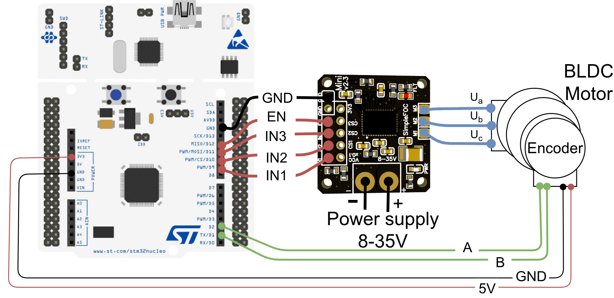
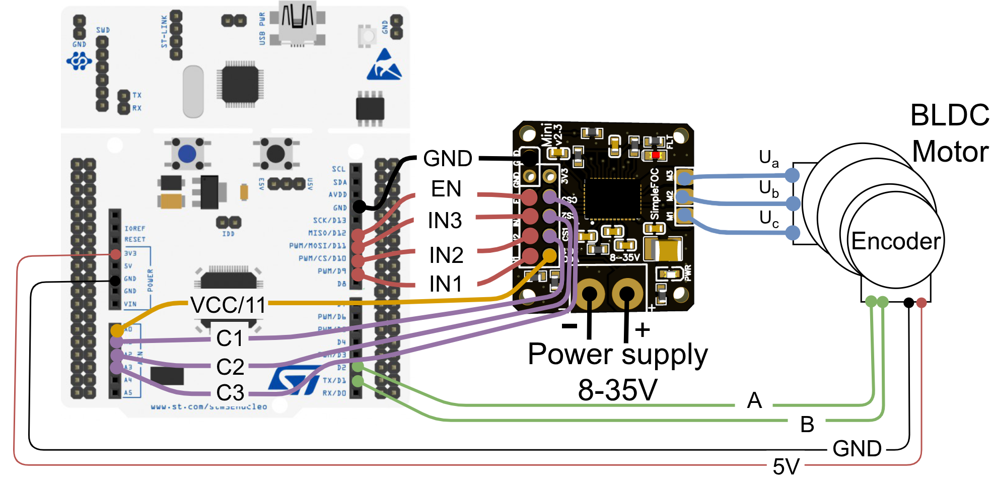
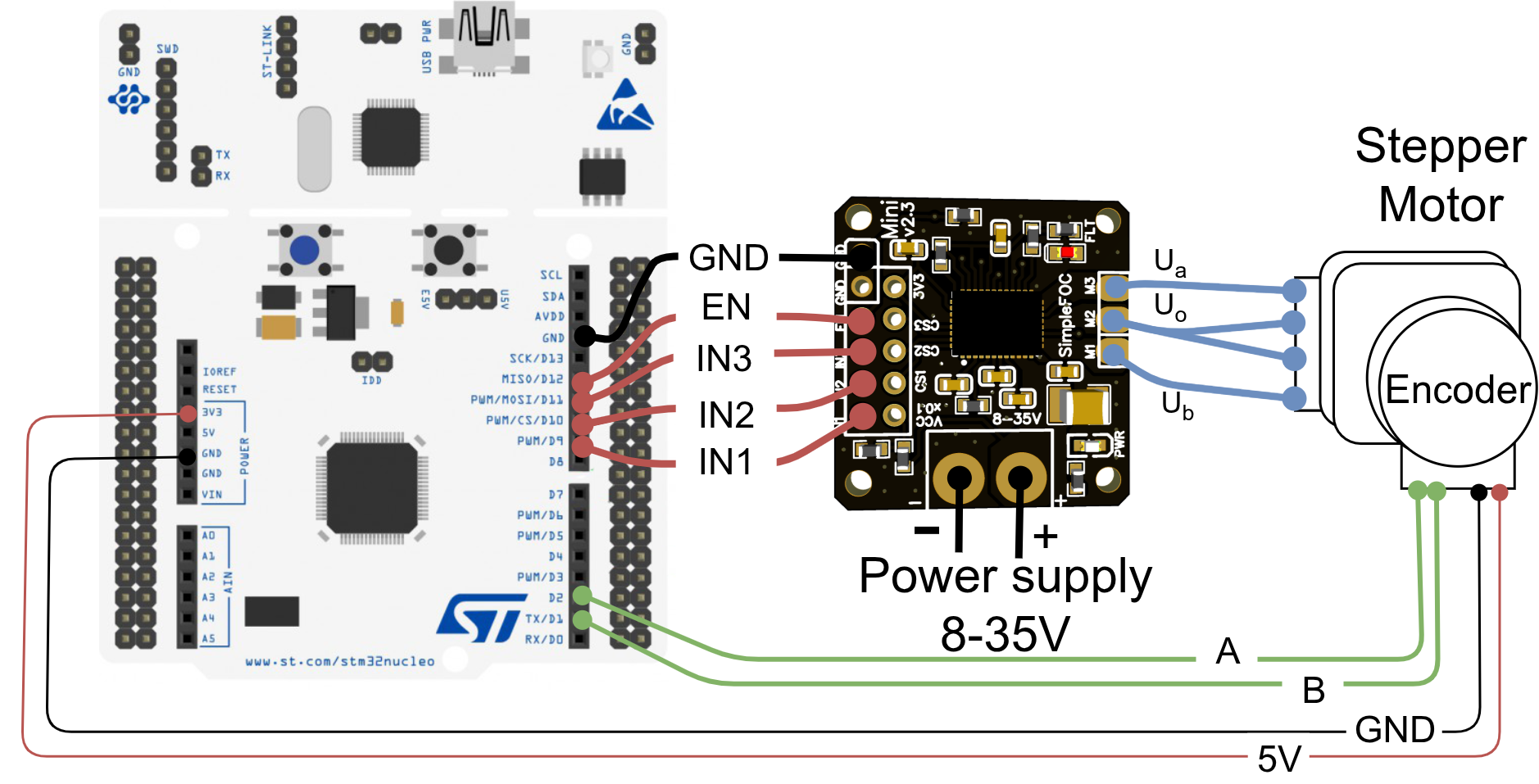
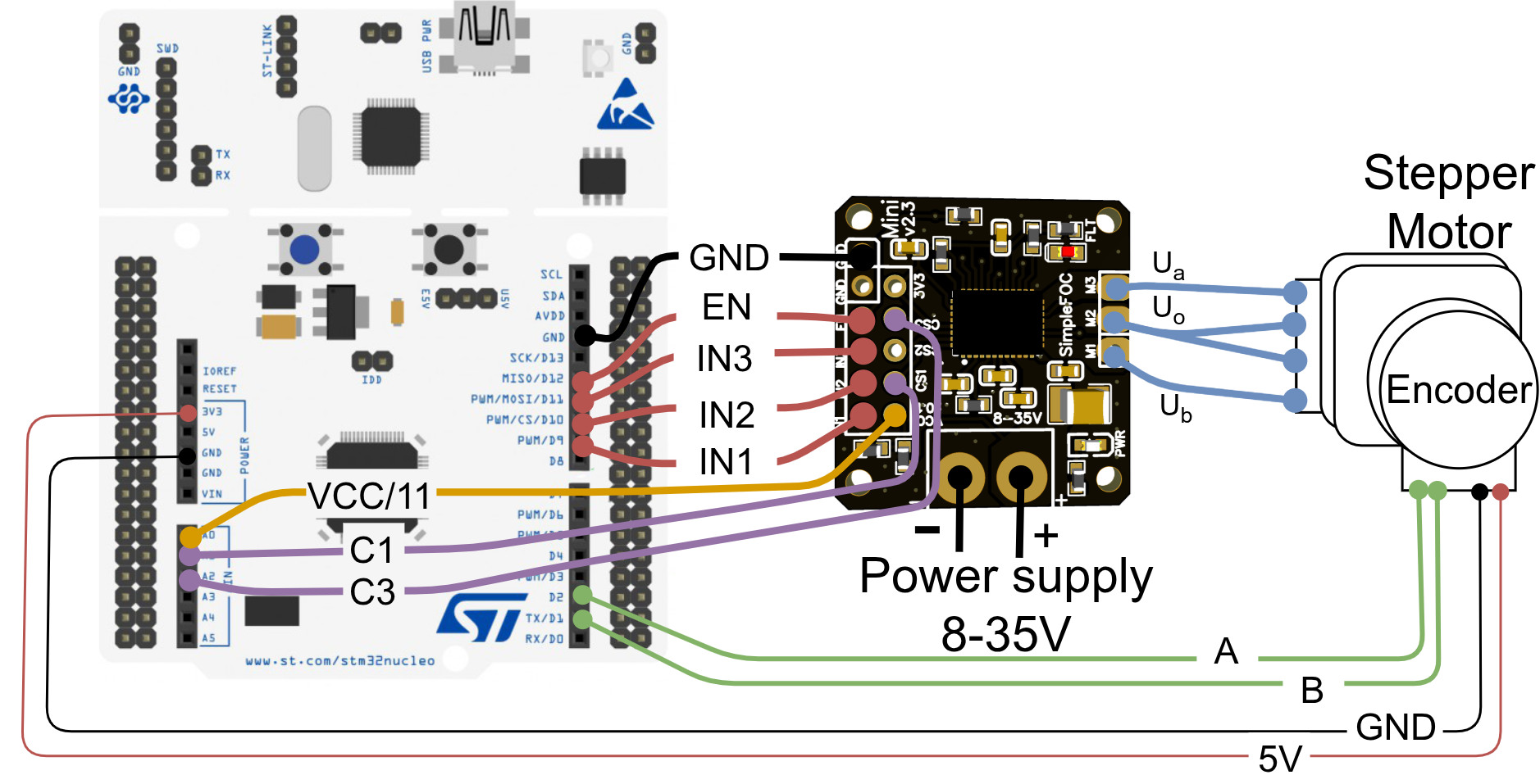
| Mini pin | IN1 | IN2 | IN3 | EN | GND |
|---|---|---|---|---|---|
| Nucleo pin | 10 | 11 | 12 | 13 | GND |
BLDCDriver3PWM driver = BLDCDriver3PWM(10, 11, 12, 13);
| Mini pin | CS1 | CS2 | CS3 |
|---|---|---|---|
| Nucleo pin | A1 | A2 | A3 |
LowsideCurrentSense cs = LowsideCurrentSense(150.0f, A1, A2, A3);
For measuring the power-supply voltage, connect the VCCx0.1 pin of the mini board to any analog input pin on the Nucleo. If using current sensing, regular analogRead will not work properly. Instead we encourage using the dedicated ADC channels for current sensing as described in the docs. To be safe use the _readRegularADCVoltage function.
float vccReading = _readRegularADCVoltage(A0); // returns the voltage at the pin A0
float vccVoltage = vccReading*11.0f; // accounting for the voltage divider ratio
Arduino UNO board
Motor type
Current sensing
Without current sensing With current sensing(not supported)
The Mini can stack onto the UNO headers from pins 9 through 12, with the Mini GND connected to Arduino GND. See the UNO library example.
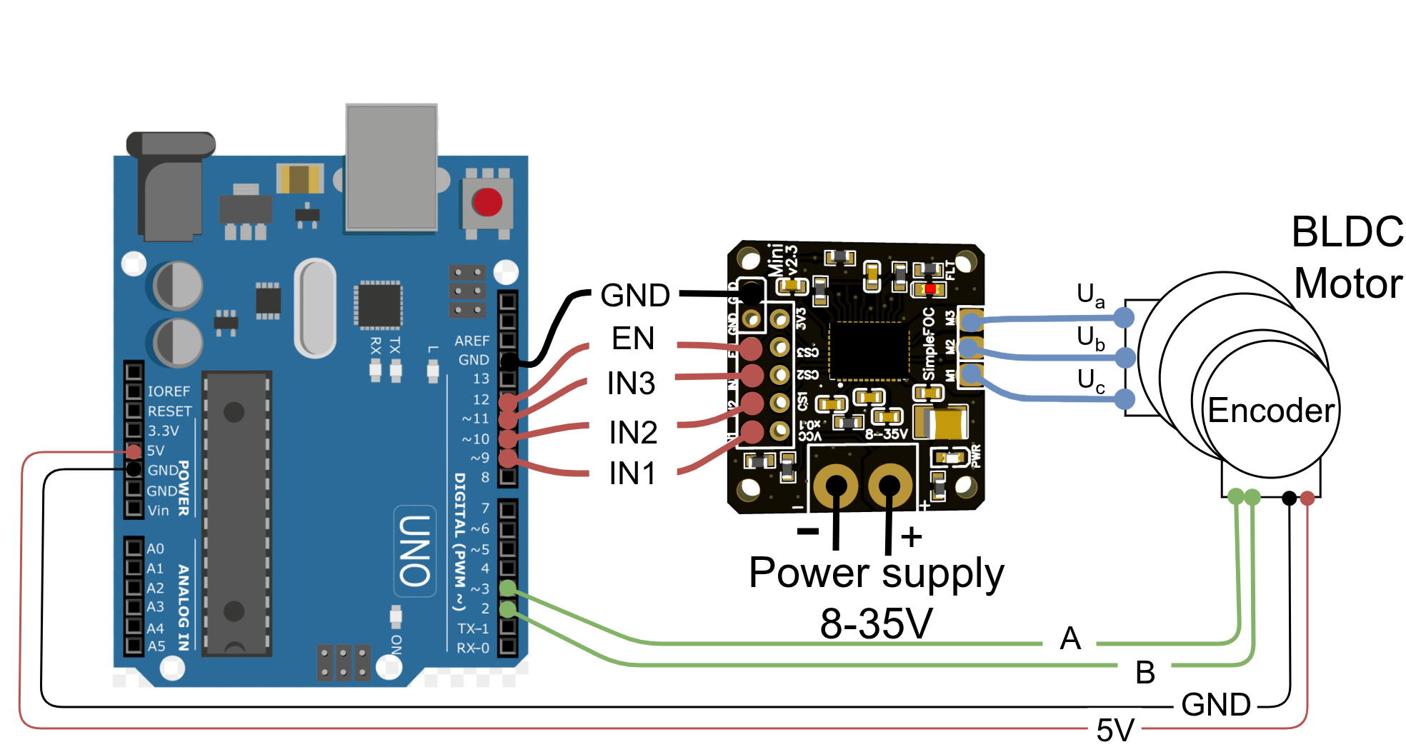
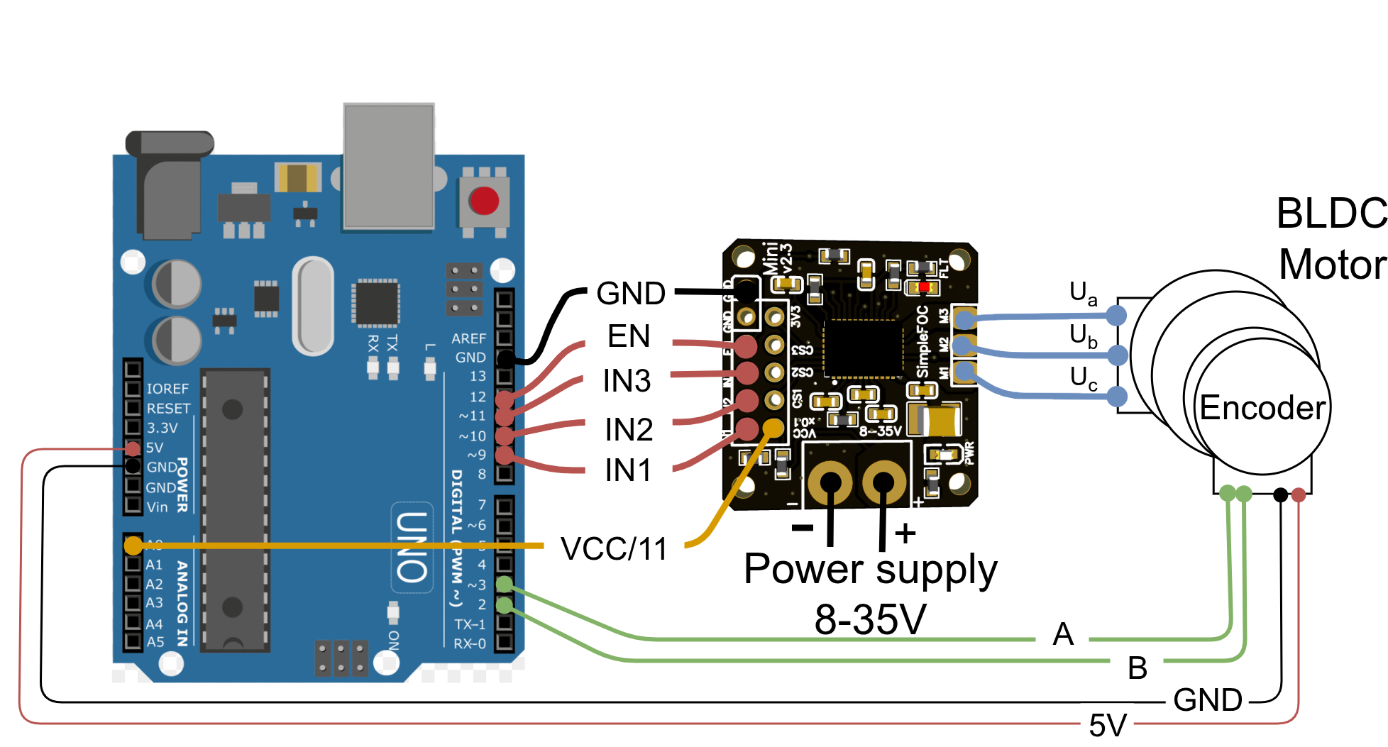
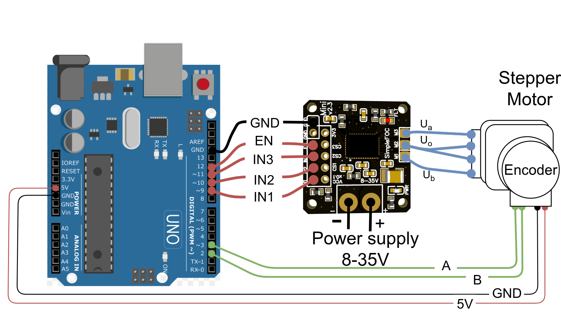
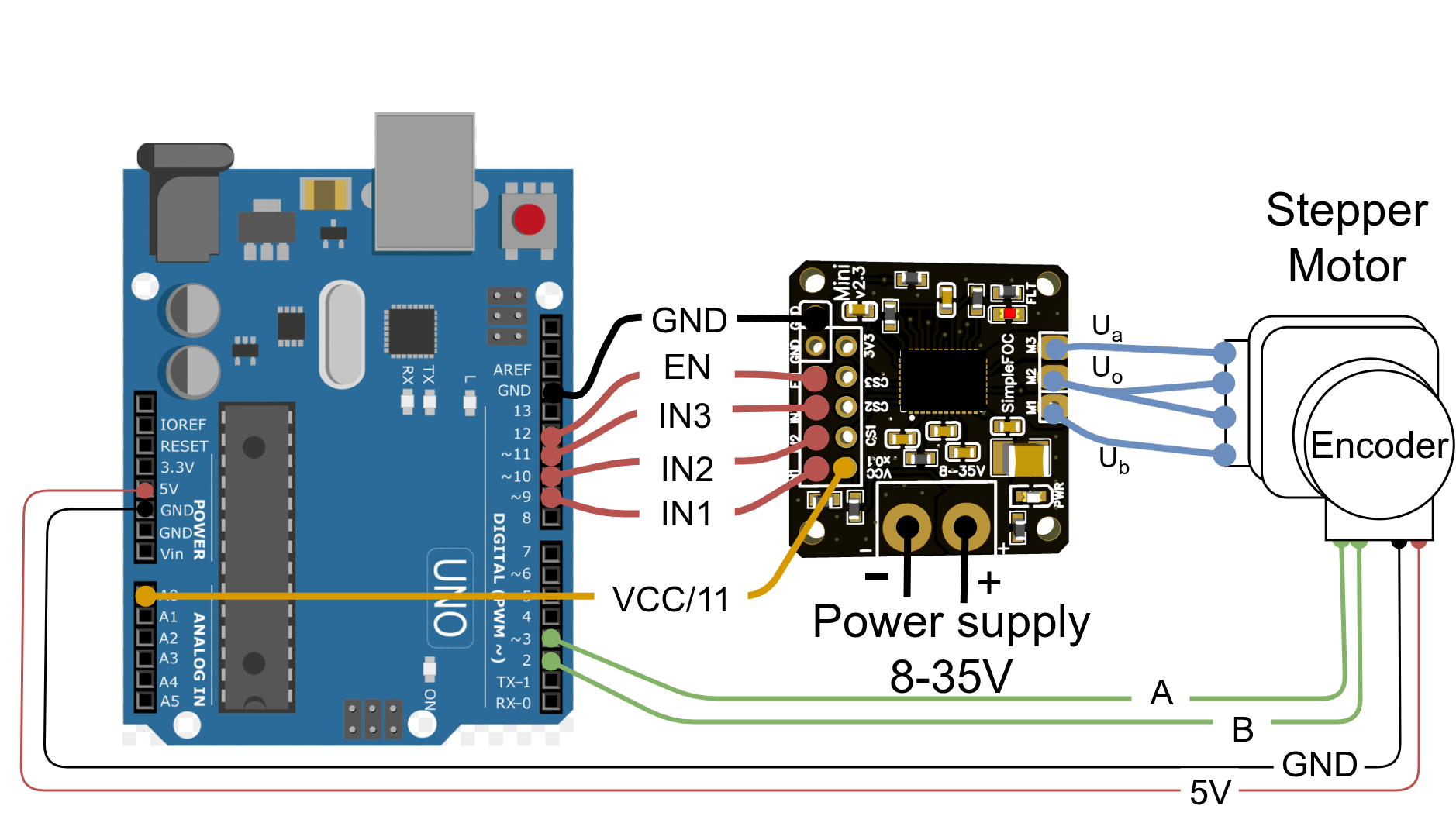
| Mini pin | IN1 | IN2 | IN3 | EN | GND |
|---|---|---|---|---|---|
| UNO pin | 9 | 10 | 11 | 12 | GND |
BLDCDriver3PWM driver = BLDCDriver3PWM(9, 10, 11, 12);
For measuring the power-supply voltage, connect the VCCx0.1 pin of the mini board to any analog input pin on the Arduino UNO. And read the voltage using the analogRead function.
float vccReading = analogRead(A0)/1023.0f*5.0f; // assuming a 5V reference voltage
float vccVoltage = vccReading*11.0f; // accounting for the voltage divider ratio
No Low-side current sensing support
Arduino UNO and other atmega based boards do not support low-side current sensing. See more details in the SimpleFOC documentation.
Bluepill board
Motor type
Current sensing
Without current sensing With current sensing
The Mini can stack onto the Bluepill headers from PB6 through PB9; connect the Mini and Bluepill grounds together.
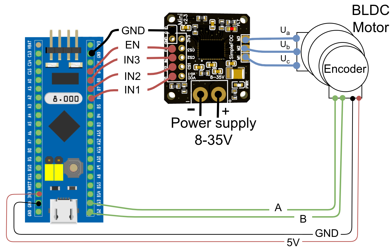
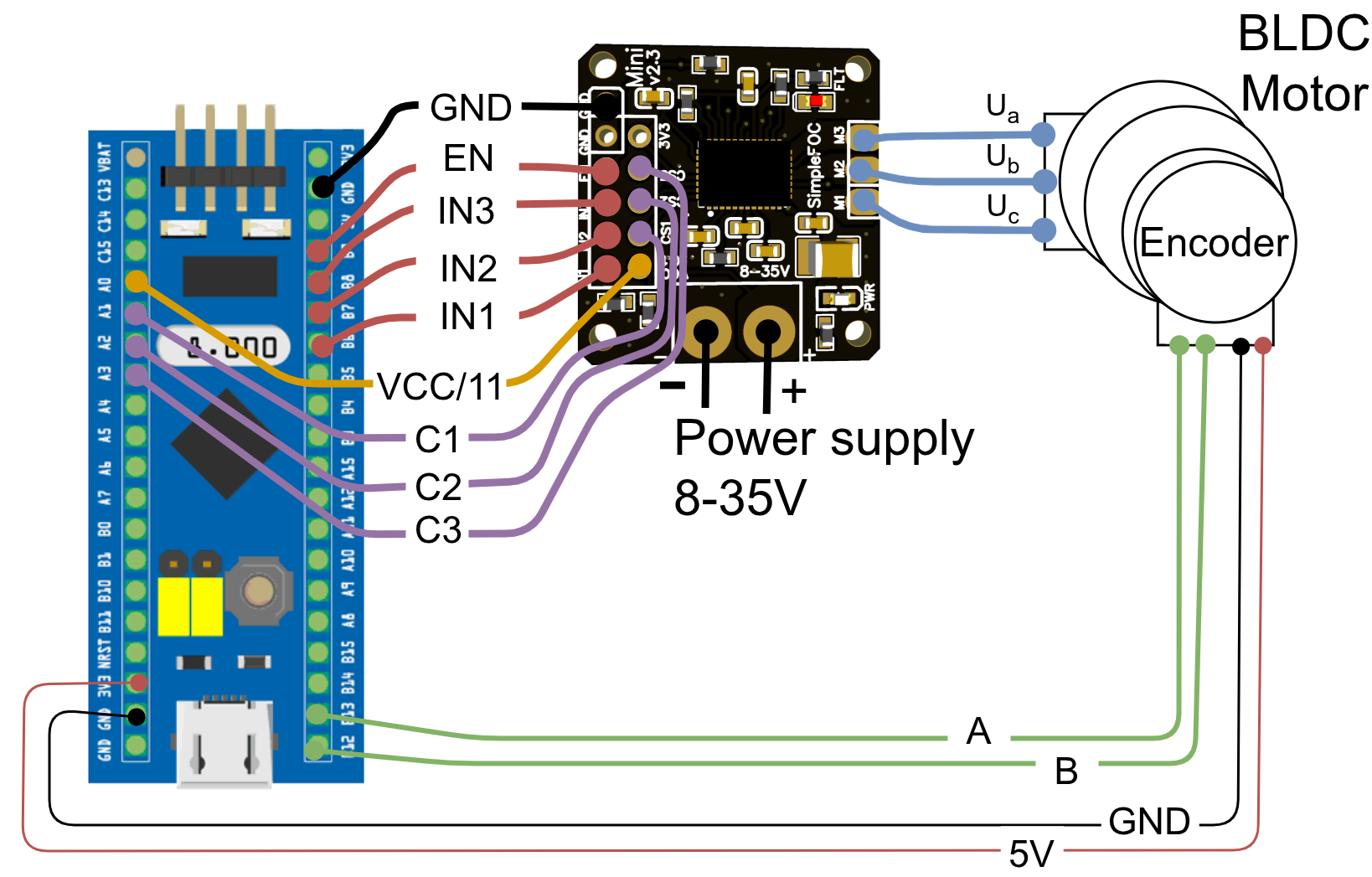
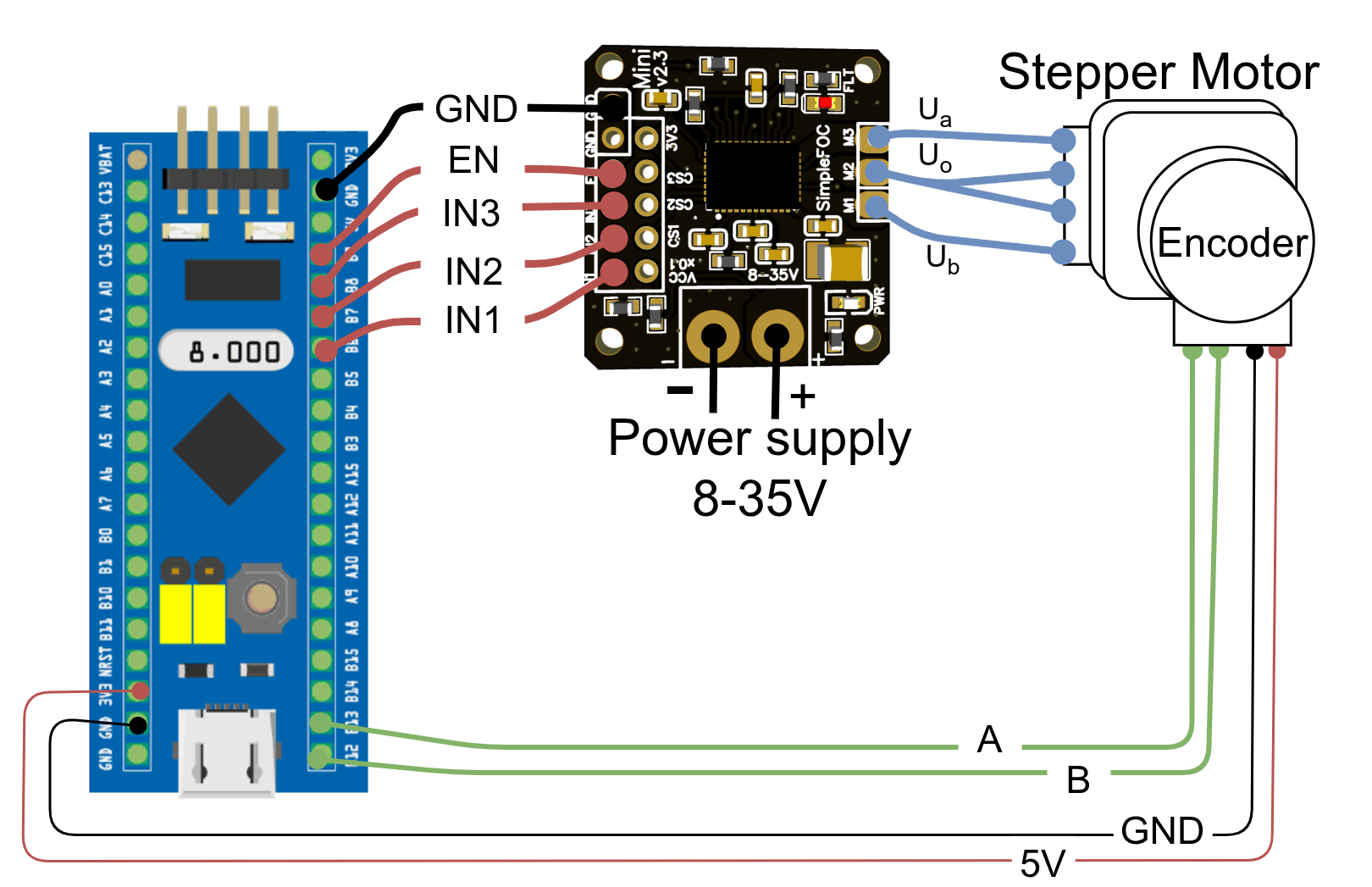
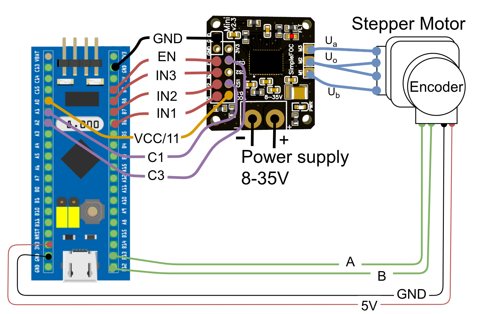
| Mini pin | IN1 | IN2 | IN3 | EN | GND |
|---|---|---|---|---|---|
| Bluepill pin | PB6 | PB7 | PB8 | PB9 | GND |
BLDCDriver3PWM driver = BLDCDriver3PWM(PB6, PB7, PB8, PB9);
| Mini pin | CS1 | CS2 | CS3 |
|---|---|---|---|
| Bluepill pin | PA1 | PA2 | PA3 |
LowsideCurrentSense cs = LowsideCurrentSense(150.0f, PA1, PA2, PA3);
For measuring the power-supply voltage, connect the VCCx0.1 pin of the mini board to any analog input pin on the Bluepill. If using current sensing, regular analogRead will not work properly. Instead we encourage using the dedicated ADC channels for current sensing as described in the docs. To be safe use the _readRegularADCVoltage function.
float vccReading = _readRegularADCVoltage(PA0); // returns the voltage at the pin PA0
float vccVoltage = vccReading*11.0f; // accounting for the voltage divider ratio
QT Py or Seeed XIAO boards
Motor type
Current sensing
Without current sensing With current sensing
The Mini can stack onto QT Py or Seeed XIAO headers using pins 8 through 10; the 3.3V pin can be used for EN. Connect the grounds together. With this wiring, the driver remains enabled and cannot be disabled through EN.
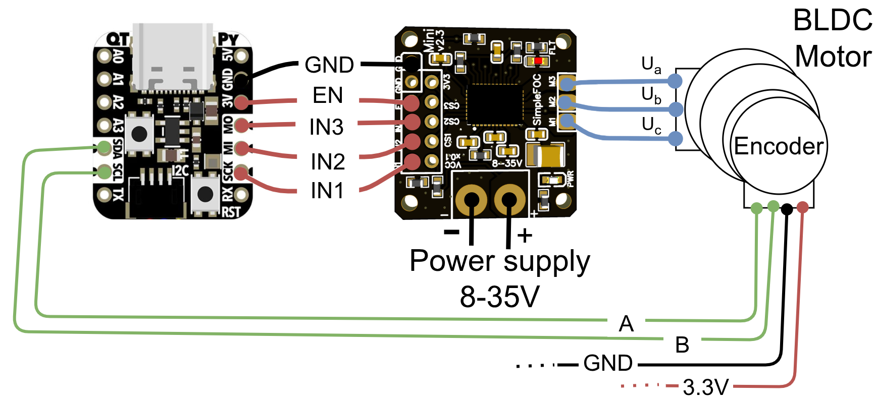
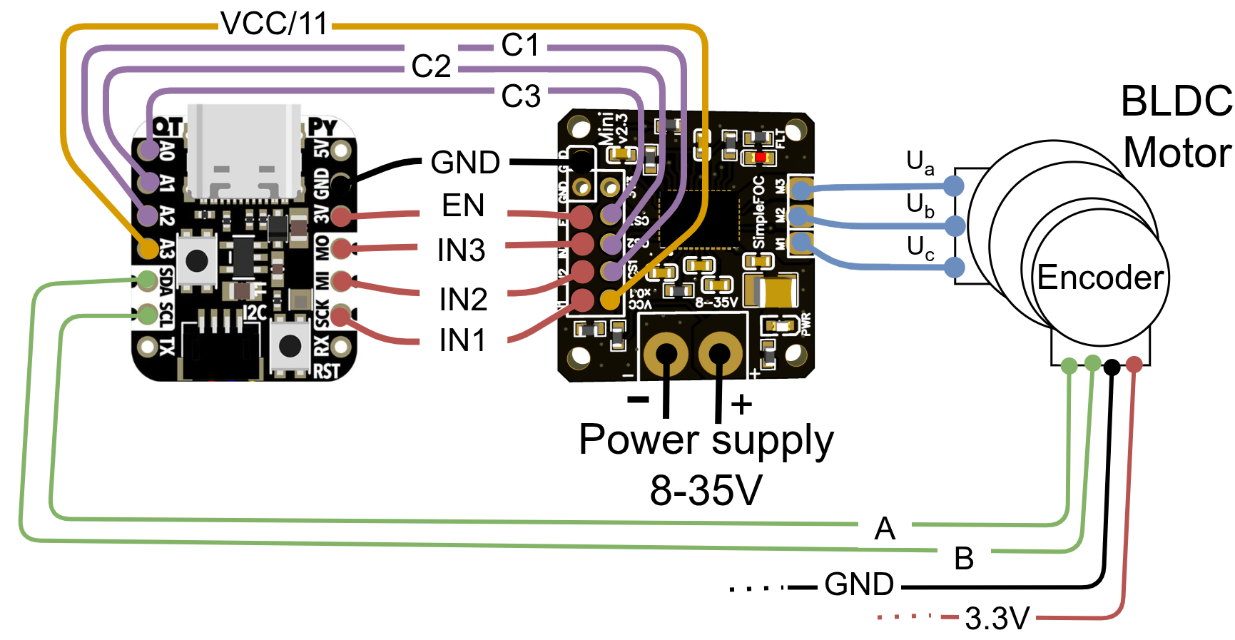
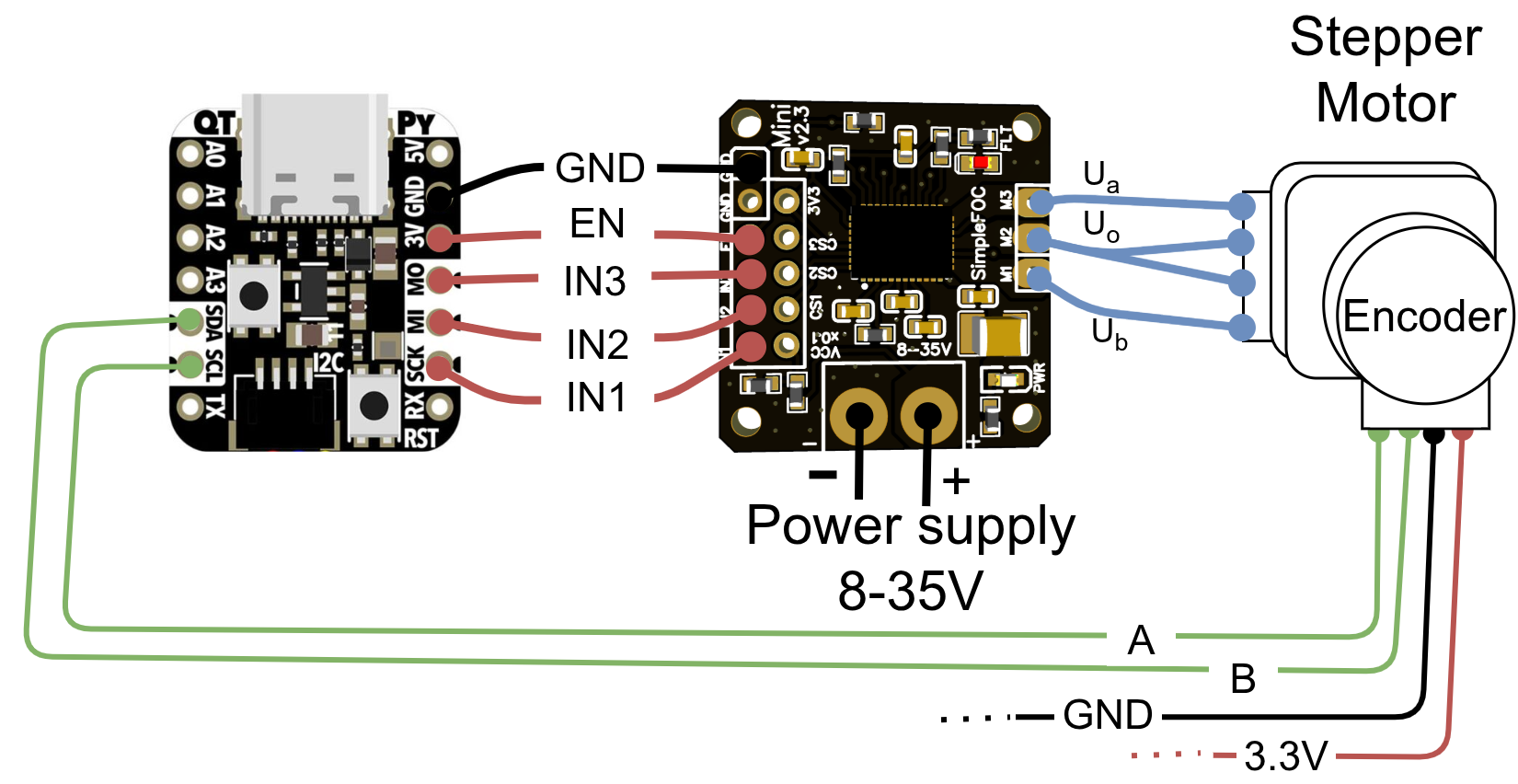
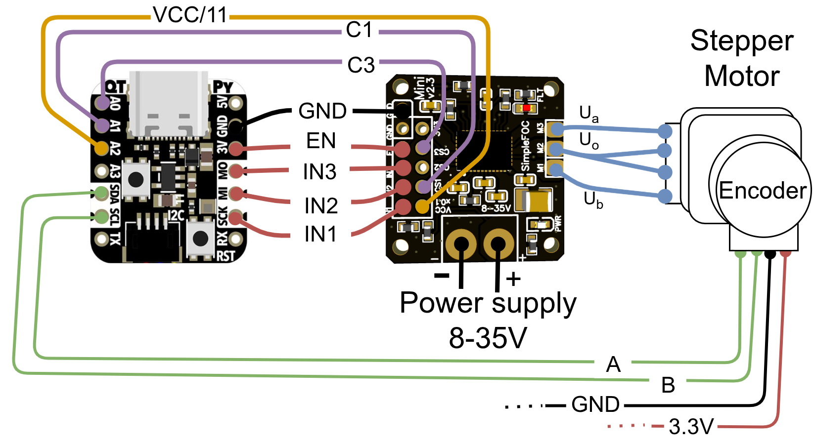
Note: Enable pin always high
With this connection setup there is no possibility to disable the driver using the `EN` pin. The driver will be always enabled.
| Mini pin | IN1 | IN2 | IN3 | EN | GND |
|---|---|---|---|---|---|
| QT Py / XIAO pin | 8 | 9 | 10 | 3.3V | GND |
BLDCDriver3PWM driver = BLDCDriver3PWM(8, 9, 10);
| Mini pin | CS1 | CS2 | CS3 |
|---|---|---|---|
| QT Py / XIAO pin | A0 | A1 | A2 |
LowsideCurrentSense cs = LowsideCurrentSense(150.0f, A0, A1, A2);
Low-side current sensing warning
Make sure to verify the compatibility of your specific QtPy variant with low-side current sensing before proceeding. See more info [here](microcontrollers).
For measuring the power-supply voltage, connect the VCCx0.1 pin of the mini board to any analog input pin on the QtPy. If using current sensing, regular analogRead will probably not work properly. Instead we encourage using the dedicated ADC channels for current sensing as described in the docs.