On this page
SimpleFOC DriveShield v1.8


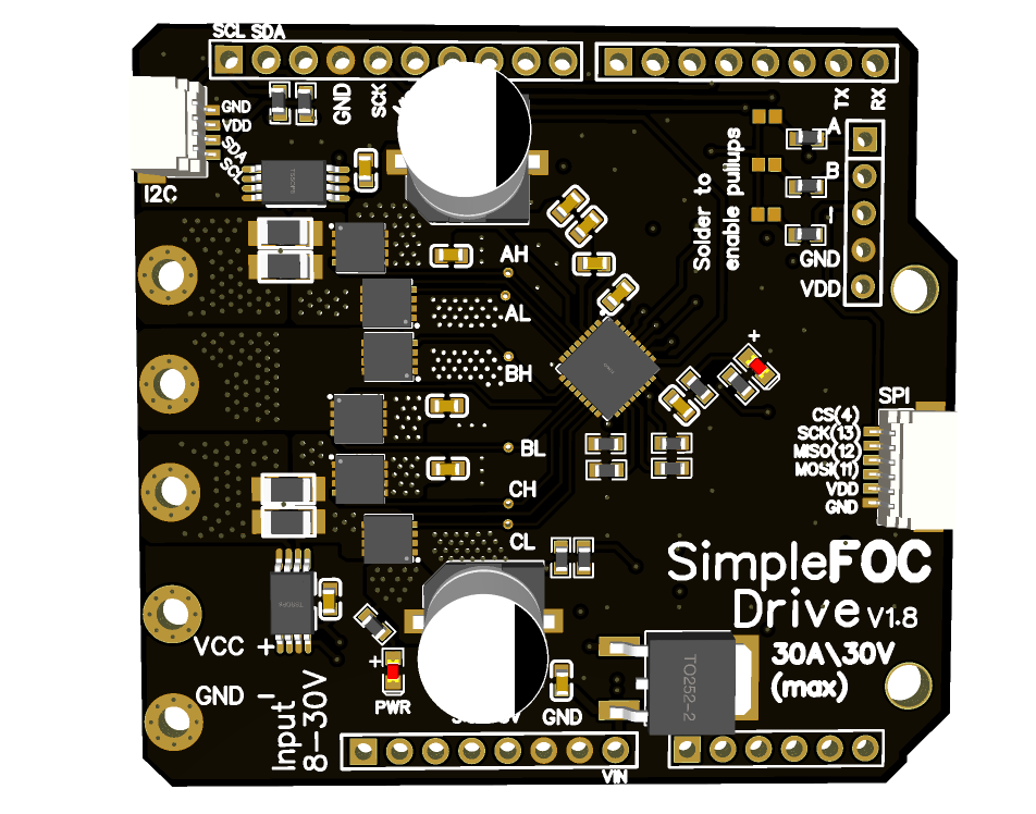
The SimpleFOC DriveShield is the big brother of the SimpleFOCShield: an open-source, low-cost BLDC driver in the form of an Arduino shield, for motors that need up to 20A continuous. It has the same philosophy, form factor and configuration as the Shield: simple to use, stackable, configured with solder pads, and fully compatible with the SimpleFOClibrary.
It is also meant as a template project for the community: a relatively simple design, made in EasyEDA with all the fabrication files available, that is easy to modify for your own driver.
Get started with your board Order from Makerfabs GitHub project
Features
- Max current: 20A continuous, 30A peak (measured)
- Supply voltage: 8-30V
- Gate driver: DRV8320H, 3PWM mode, hardware configured
- Protections: undervoltage lockout, charge pump fault, MOSFET overcurrent and short circuit, gate driver fault, overtemperature
- Fault LED, and an optional fault output to the microcontroller
- MOSFETs: BSZ0904NSI, 30V / 75A, standard 3x3mm footprint, easy to replace
- Cooling: 2oz copper outer layers on the Makerfabs boards, room for an optional 23 x 23mm heatsink on the power stage
- Inline current sensing: INA240A1 amplifiers (gain 20) with 2mΩ shunts, ±40A range at 3.3V
- Power supply voltage sensing: voltage divider (1/11)
- Integrated 8V regulator: powers the microcontroller board through
VIN(v1.8+) - Stackable: run two motors from one microcontroller
- Encoder/Hall interface: 3.3kΩ pull-ups, configurable
- I2C interface: 4.7kΩ pull-ups, configurable
- Connectors: STEMMA QT/QWIIC for I2C, JST for SPI sensors
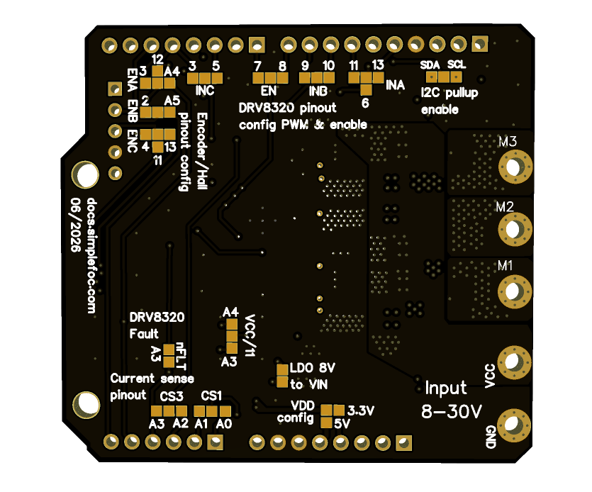
- Configurable pinout: solder pads, same options as the SimpleFOCShield
- Arduino headers: Arduino UNO, Arduino MEGA, STM32 Nucleo-64, ESP32 boards with UNO headers, …
- Open source: designed in EasyEDA - EasyEDA project, all fabrication files on GitHub
- Low cost: about 25-40€
Shield or DriveShield?
Both boards share the footprint, the headers, the solder pad configuration and the connectors, so moving from one to the other is easy. The difference is the power stage:
| Feature | SimpleFOCShield v4 | SimpleFOC DriveShield v1.8 |
|---|---|---|
| Board | 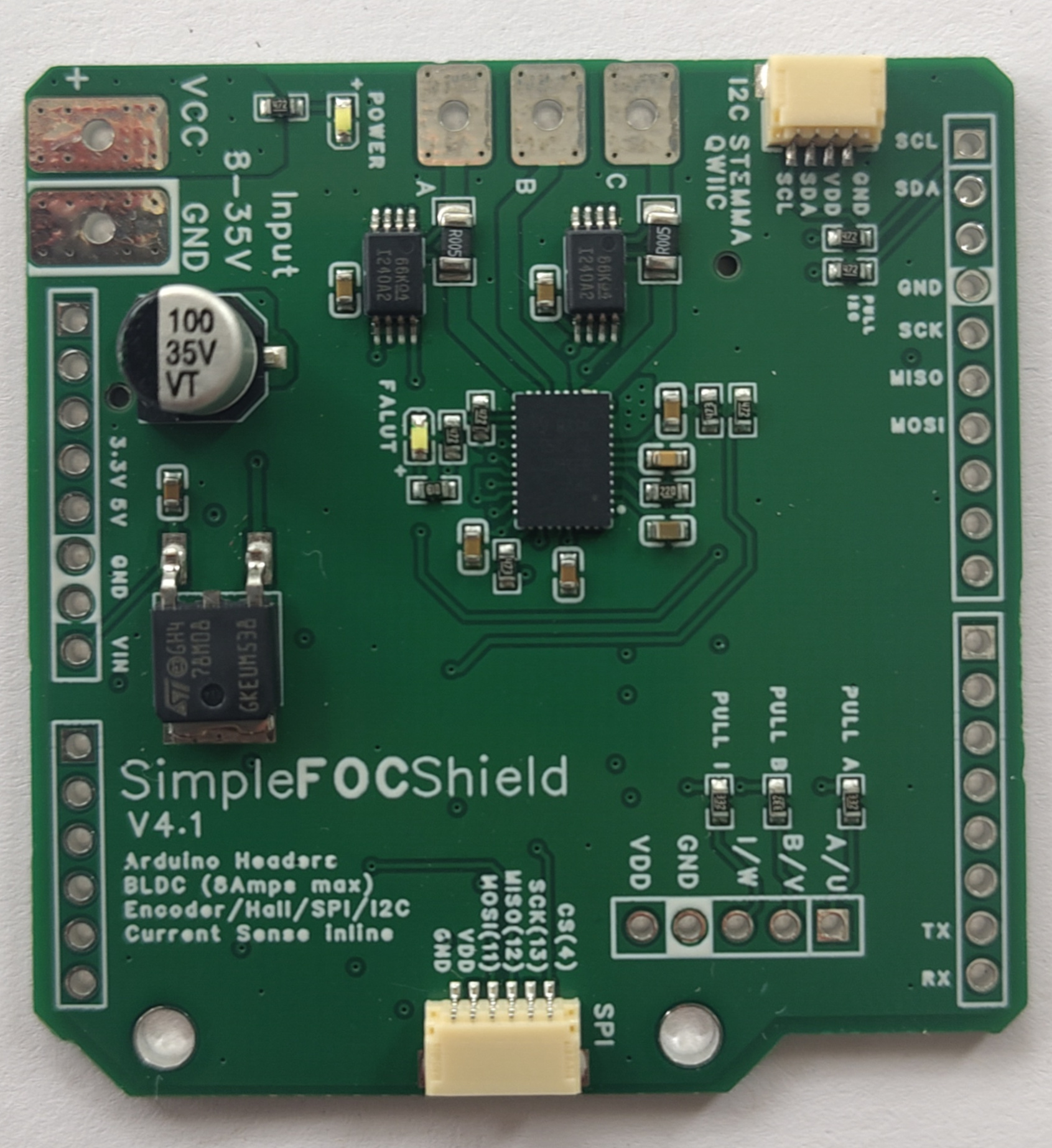 | 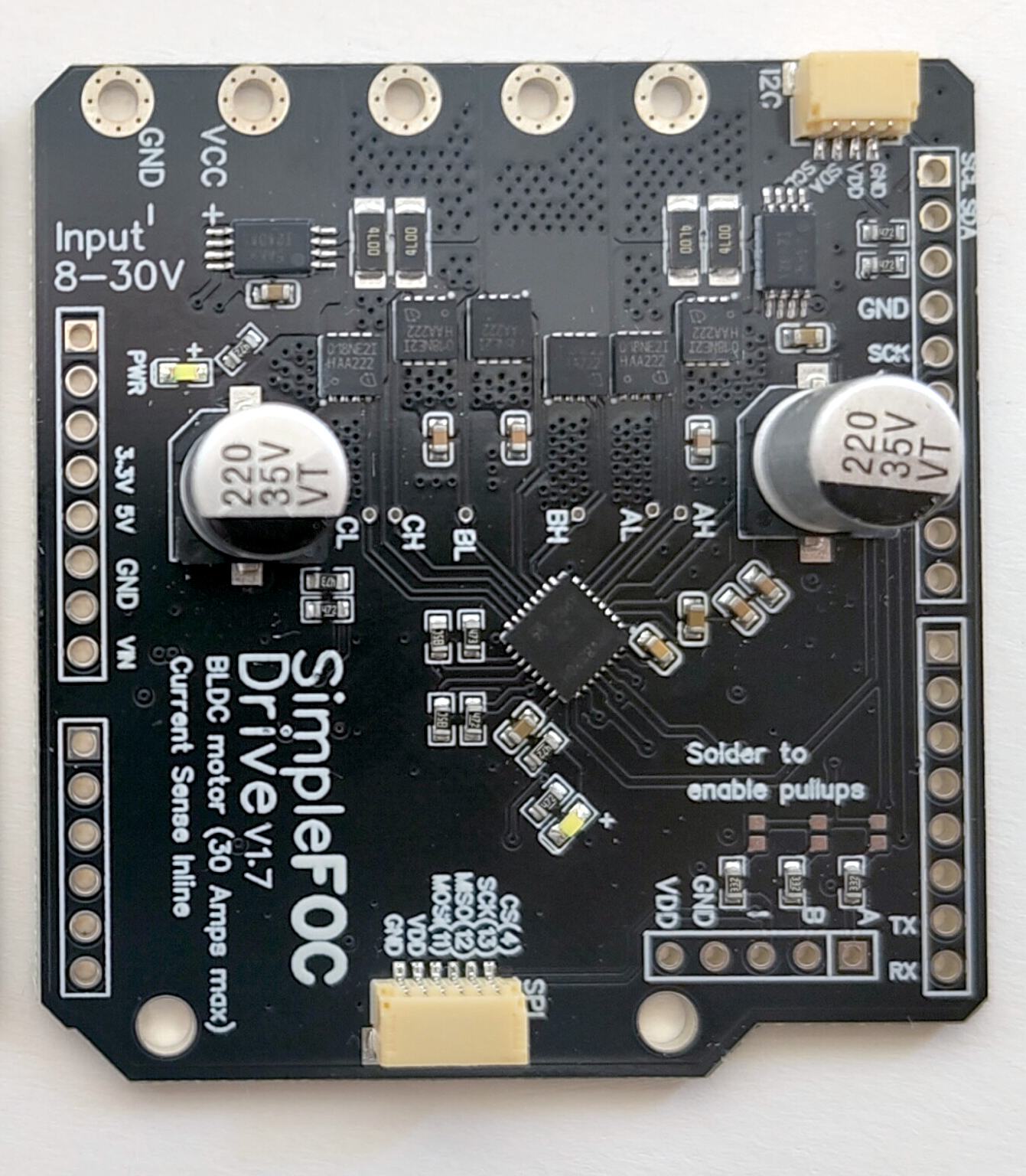 |
| Power stage | DRV8316 integrated driver | DRV8320H gate driver + 6x BSZ0904NSI MOSFETs |
| Continuous current | 3-5A | 20A |
| Peak current | 8A | 30A (measured) |
| Supply voltage | up to 35V | 8-30V |
| Current sensing | INA240A2, 5mΩ, ±6.6A / ±10A | INA240A1, 2mΩ, ±40A |
| Voltage sensing | ✔️ | ✔️ |
| Fault output to MCU | ❌ (LED only) | ✔️ optional, pin A3 |
| Onboard 8V regulator | ✔️ | ✔️ (v1.8+) |
| STEMMA QT / SPI connectors | ✔️ | ✔️ |
| Footprint | 56 x 53mm | 56 x 53mm |
| Typical motors | Gimbal motors, small drone motors | Drone motors, larger BLDC motors, robot joints |
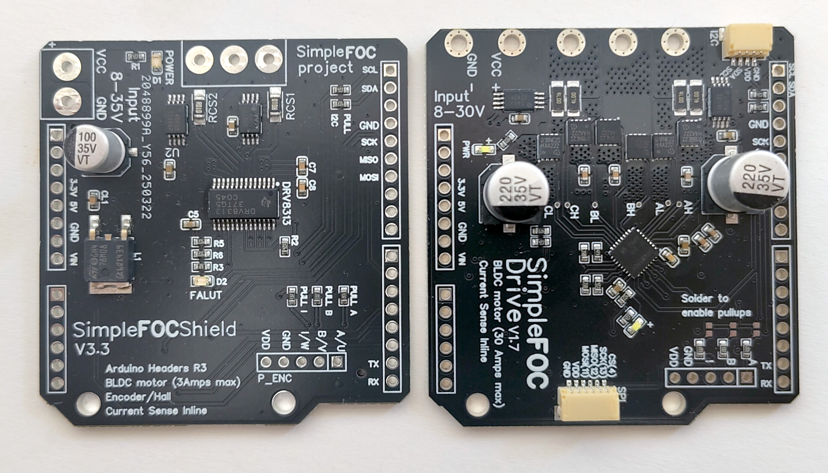
As a rule of thumb: if your motor needs more than a few Amps, or has a phase resistance well below 1Ω, use the DriveShield.
Thermal performance
The board can measure currents up to about 40A, and is meant for applications up to about 20A continuous. At higher currents it gets hot, depending on the PCB copper thickness and the cooling.
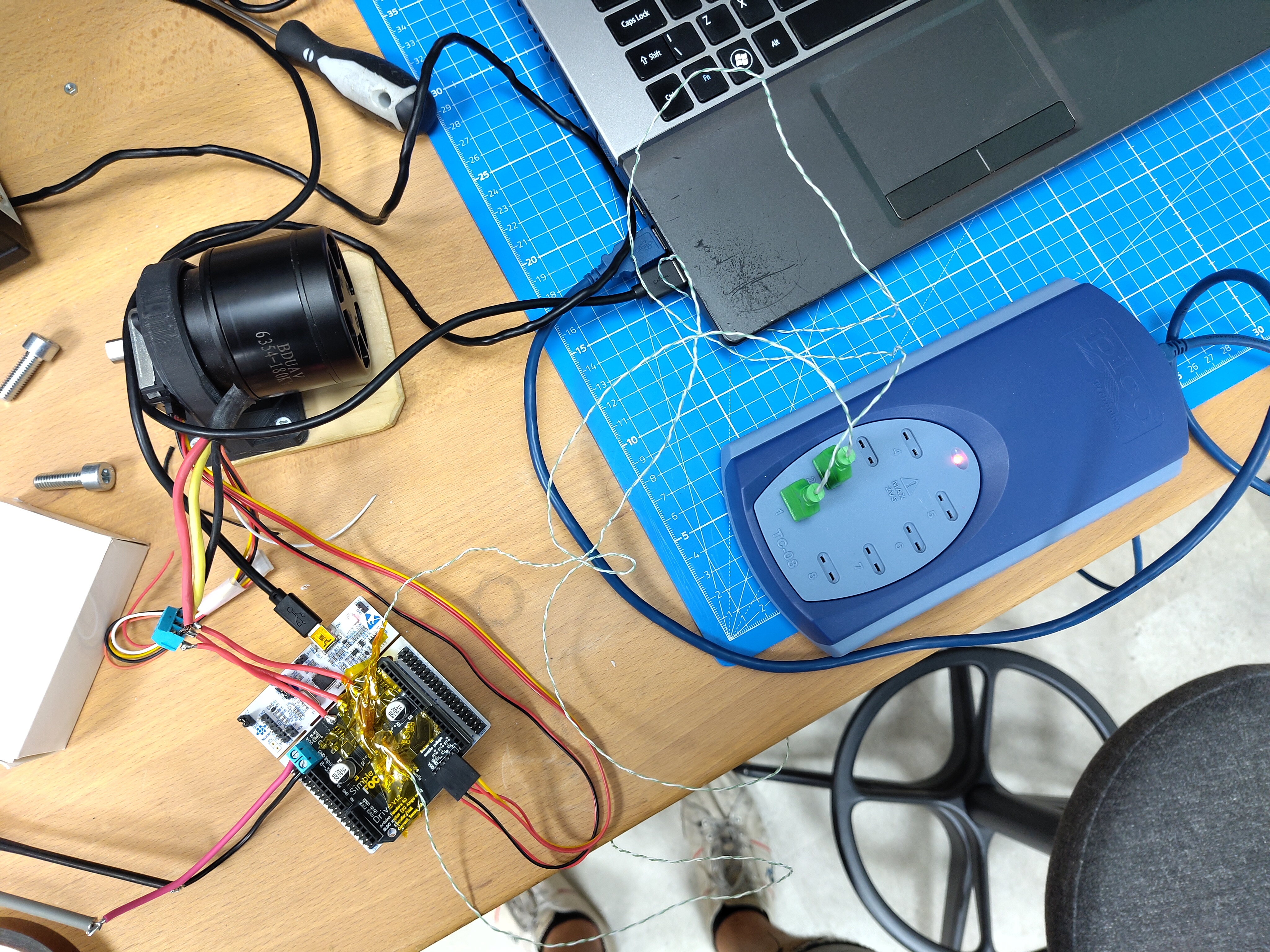
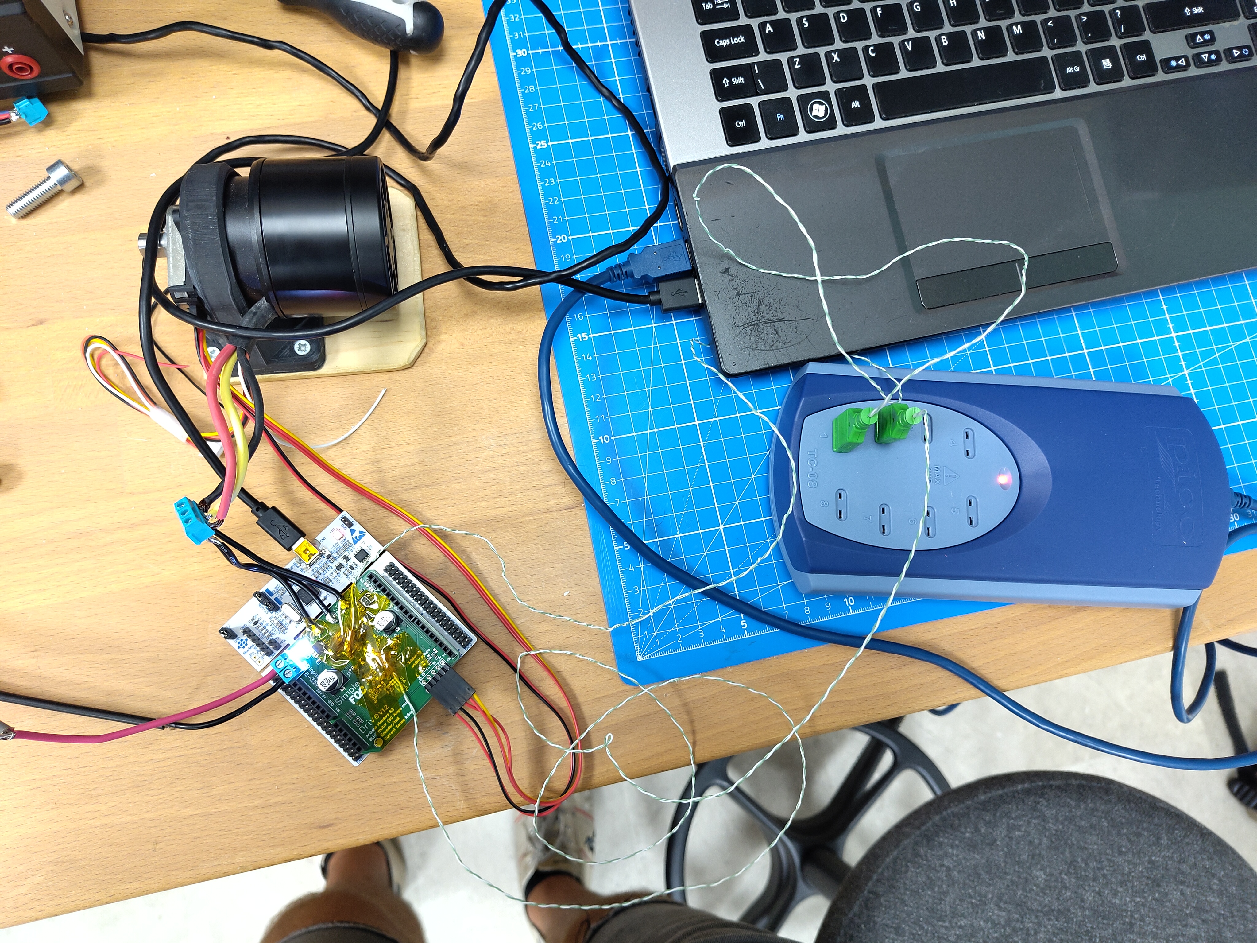
The temperatures were measured on the top of the board, on the DRV8320H and the MOSFETs, with a 24V supply, at about 25°C ambient, with no heatsink. The motor ran slowly in open loop with a constant current, for two PCB versions:
- Standard 4-layer: 1oz (35µm) outer layers, 0.5oz inner layers
- Thick 4-layer: 2oz (70µm) outer layers, 0.5oz inner layers
| Current | MOSFETs, standard | MOSFETs, thick | DRV8320H, standard | DRV8320H, thick |
|---|---|---|---|---|
| 10A | 57°C | 53°C | 50°C | 52°C |
| 15A | 78°C | 68°C | 62°C | 62°C |
| 20A | 125°C | 100°C | 82°C | 82°C |
The MOSFETs are rated up to 150°C and the DRV8320H up to 125°C, so the board can run at 20A without extra cooling, but with little margin.
The boards made by Makerfabs use the thick PCB, with 2oz copper on the outer layers. If you make the board yourself, choose 2oz outer copper when ordering the PCB.
Above 15A continuous
Use a heatsink on the power stage, and a PCB with thick copper (2oz outer layers).
Heatsink
The board is designed to take a 23 x 23mm heatsink on top of the power stage, covering the six MOSFETs and the DRV8320H, if your application needs it (the white area below).
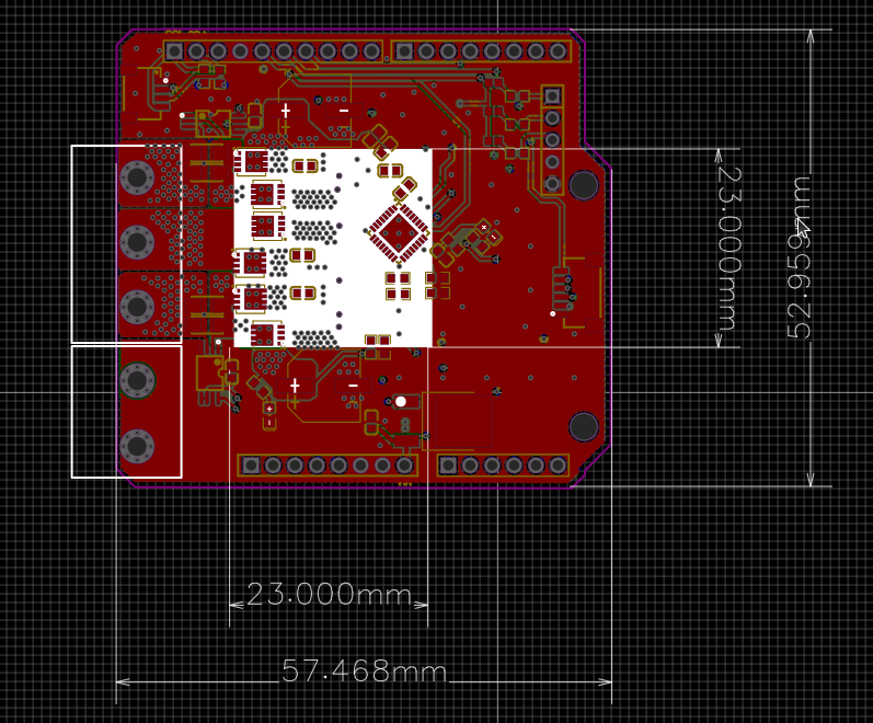
A small adhesive aluminium heatsink is enough, for example the RS PRO 750-0894: 23 x 23 x 6mm, 22K/W, with adhesive thermal foil.
- Make sure the heatsink doesn’t touch any of the exposed pads or components around the power stage.
- A small fan blowing over the board helps a lot more than a bigger heatsink.
Release history
| Version | Date | Changes |
|---|---|---|
| v0.1 | 05/24 | Test version: DRV8300 gate driver, SE3082G dual MOSFETs, ACS712 current sensing, 20V max |
| v1.0 | 06/24 | DRV8320H gate driver, 30V max |
| v1.1 | 07/24 | 3x3mm BSZ09x MOSFETs instead of SE3082G |
| v1.2 | 08/24 | First release: 4-layer PCB, stacking (solder pads), configurable pull-ups |
| v1.7 | 02/26 | STEMMA QT and SPI connectors, INA240 current sensing, power supply voltage sensing |
| v1.8 | 06/26 | 8V regulator to power the microcontroller from VIN |
How to get one
- Order the assembled board from Makerfabs. Makerfabs makes the board with 2oz outer copper layers, the thick version from the thermal measurements.
- Make it yourself: the Gerber, BOM and pick and place files are in the GitHub repository, and the EasyEDA project can be ordered directly from JLCPCB. The process is the same as for the Shield v4.