On this page
Getting started with the SimpleFOC DriveShield
The DriveShield is set up and programmed the same way as the SimpleFOCShield. This page covers what is specific to the DriveShield; for a step-by-step introduction to the code, follow the Shield code guide and use the DriveShield values from this page.
1. Configure the solder pads
The configuration pads are on the bottom side of the board, each labelled with the signal and the possible pins.
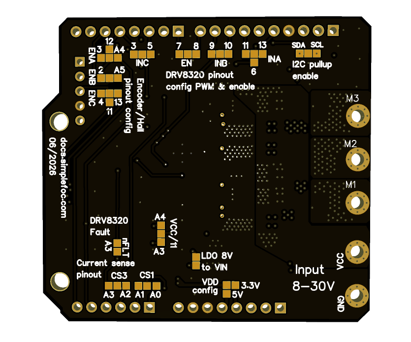
Solder exactly one pin for each signal you use:
| Signal | Silkscreen | Possible pins |
|---|---|---|
| PWM A | INA | 6, 11, 13 |
| PWM B | INB | 9, 10 |
| PWM C | INC | 3, 5 |
| Enable | EN | 7, 8 |
| Encoder A / Hall U | ENA | 3, 12, A4 |
| Encoder B / Hall V | ENB | 2, A5 |
| Encoder I / Hall W | ENC | 4, 11, 13 |
| Current sense, PWM A phase | CS3 | A2, A3 |
| Current sense, PWM C phase | CS1 | A0, A1 |
| Supply voltage / 11 | VCC/11 | A3, A4 |
| DRV8320 fault output | nFLT | A3 |
Different from the Shield: encoder A and B
The analog options of encoder A and B are swapped compared to the SimpleFOCShield: on the DriveShield encoder A can use
A4and encoder BA5. All the other pads have the same options as on the Shield.
The other pads:
- VDD config (
3.3V/5V): the logic voltage. It powers the current sense amplifiers, the pull-ups and the sensor connectors, so set it to match your microcontroller: 5V for Arduino UNO and MEGA, 3.3V for STM32 Nucleo and ESP32. - LDO 8V to VIN: powers the microcontroller board from the motor supply through its
VINpin. Enable it on one board only when stacking. The supply must be at least about 10V. - I2C pull-up enable (
SDA,SCL): 4.7kΩ pull-ups for I2C sensors. Enable them on one board only when stacking. - Encoder pull-ups: 3.3kΩ pull-ups for encoder and Hall sensor channels, needed by open-collector sensors.
Pins A3 and A4 have several possible uses (current sense, voltage sense, fault, encoder A), so check that you don’t solder two signals to the same pin. On Arduino UNO, A4 and A5 are also the I2C pins.
Suggested pinout: single board
| Signal | PWM A | PWM B | PWM C | Enable | Enc. A | Enc. B | Enc. I | CS3 | CS1 | Voltage |
|---|---|---|---|---|---|---|---|---|---|---|
| Pin | 6 | 10 | 5 | 8 | 3 | 2 | 4 | A2 | A0 | A3 |
This is the same as the suggested Shield pinout, so the code from the Shield guide works with only the current sense values changed. If you want the fault output on A3, move the voltage sensing to A4.
Stacking two boards
Two DriveShields can be stacked to drive two motors. Use different pins for each board, e.g. the second board on PWM 13, 9, 3, enable 7, encoder 12, A5, 11 and current sense A3, A1. With current sensing on both boards, A3 is used, so the fault output can’t be used, and the voltage sensing can go on A4 of one board only if encoder A doesn’t use it. See the Shield stacking pinouts for the constraints of each microcontroller.
2. Connect the hardware
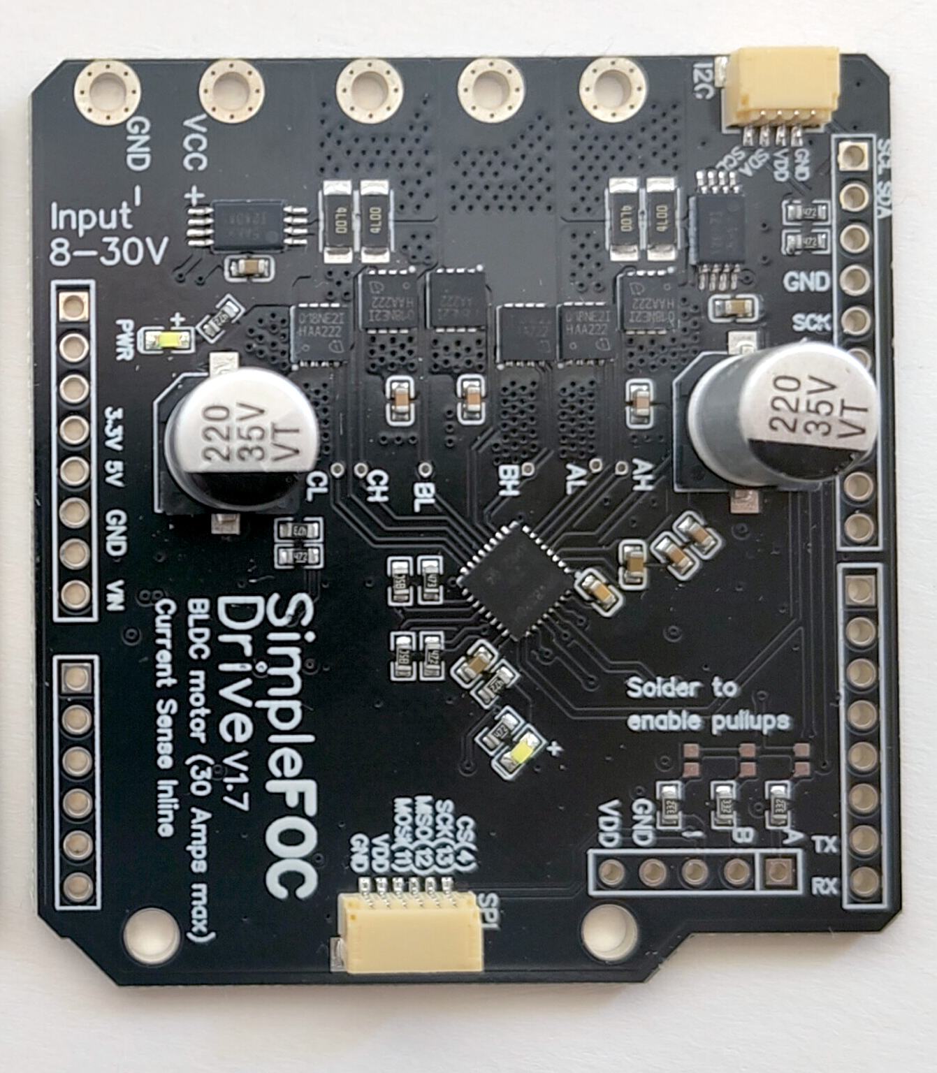
Power supply
- Connect the supply to the
VCCandGNDterminals. The supply voltage range is 8-30V. - The DriveShield can draw tens of Amps, so use thick wires and a supply that can deliver the current your motor needs. A supply with current limiting is a good idea for the first tests.
- The MOSFETs are rated for 30V: don’t use a 30V supply with a large motor that can brake regeneratively, as the braking can push the voltage above the supply.
Motor
Connect the three motor phases to the M1, M2 and M3 terminals, in any order:
| Terminal | Driven by | Current sense |
|---|---|---|
M3 | PWM A (INA) | CS3 |
M2 | PWM B (INB) | - |
M1 | PWM C (INC) | CS1 |
The motor phase order only changes the direction of rotation, which initFOC() detects automatically. The table matters when you’re debugging, for example when measuring the current of one phase.
Thermal limits
For currents above 15A continuous, add a 23 x 23mm heatsink on the power stage, see the thermal measurements and the heatsink section. Always set
motor.current_limitin the code.
Sensors
The sensor connections are the same as on the Shield:
- Encoders and Hall sensors: the 5-pin
P_ENCheader, withA,B,I,VDDandGND - SPI magnetic sensors: the 6-pin JST connector, chip select on pin
4 - I2C magnetic sensors: the 4-pin STEMMA QT/QWIIC connector
See the Shield connection guide for the connector pinouts.
3. Write the code
The code is the same as for the SimpleFOCShield, except for the current sensing. The DriveShield uses INA240A1 amplifiers with a gain of 20 and 2mΩ shunts (two 4mΩ in parallel):
// shunt resistor [Ω], amplifier gain, CS3 (PWM A phase), not measured, CS1 (PWM C phase)
InlineCurrentSense current_sense = InlineCurrentSense(0.002f, 20.0f, A2, _NC, A0);
The measurement range is ±41A with VDD at 3.3V. During initFOC(), the library checks which current sense pin belongs to which phase and corrects the order and the sign if needed.
For a step-by-step introduction, from the open loop test to FOC current control and the web controller, follow the Shield code guide with this current sense line.
Tip: low-side current sensing class
As on the Shield, the inline amplifiers can also be read with the
LowsideCurrentSenseclass on STM32, ESP32 and SAMD21, which makes the FOC loop faster:LowsideCurrentSense(0.002f, 20.0f, A2, _NC, A0). See the Shield code guide.
Fault output
If you soldered the nFLT pad, pin A3 goes low when the DRV8320H detects a fault (undervoltage, overcurrent, short circuit, overtemperature). The fault LED on the board shows the same state. You can read it in your code and stop the motor:
// in setup()
pinMode(A3, INPUT);

// in loop()
if (digitalRead(A3) == LOW) {
  motor.disable();
  Serial.println("Driver fault!");
}
To clear the fault, remove its cause and disable and re-enable the driver (motor.enable()), or power-cycle the board.
Full code
FOC current control with voltage sensing and the full Commander interface for the web controller, for an STM32 Nucleo-64, ESP32 or another board with enough flash. Set VDD to 3.3V. Choose your sensor:
Encoder SPI magnetic sensor I2C magnetic sensor Hall sensors
#include <SimpleFOC.h>
// BLDC motor: pole pairs
BLDCMotor motor = BLDCMotor(7);
// driver: PWM A, B, C, enable
BLDCDriver3PWM driver = BLDCDriver3PWM(6, 10, 5, 8);
// current sense: 2mΩ shunts (2x 4mΩ in parallel), INA240A1 gain 20
// CS3 on A2 measures the phase of PWM A, CS1 on A0 the phase of PWM C
InlineCurrentSense current_sense = InlineCurrentSense(0.002f, 20.0f, A2, _NC, A0);
// encoder on P_ENC: A, B, pulses per revolution
Encoder sensor = Encoder(3, 2, 2048);
void doA() { sensor.handleA(); }
void doB() { sensor.handleB(); }
// supply voltage sensing: VCC/11 on A3
float readSupplyVoltage() {
return analogRead(A3) * 3.3f / 1023.0f * 11.0f;
}
// commander interface, compatible with the web controller
Commander command = Commander(Serial);
void doMotor(char* cmd) { command.motor(&motor, cmd); }
void setup() {
Serial.begin(115200);
SimpleFOCDebug::enable(&Serial);
// sensor
sensor.init();
sensor.enableInterrupts(doA, doB);
motor.linkSensor(&sensor);
// driver
float vbus = readSupplyVoltage();
// fall back to 24V if the voltage sensing pad is not soldered
driver.voltage_power_supply = vbus > 6 ? vbus : 24;
driver.init();
motor.linkDriver(&driver);
// current sensing
current_sense.linkDriver(&driver);
current_sense.init();
motor.linkCurrentSense(¤t_sense);
// FOC current torque control
motor.torque_controller = TorqueControlType::foc_current;
motor.controller = MotionControlType::torque;
motor.current_limit = 10; // Amps, set to what your motor can handle
// monitoring for the web controller
motor.useMonitoring(Serial);
motor.monitor_start_char = 'M';
motor.monitor_end_char = 'M';
motor.monitor_downsample = 0; // disabled at start, enable from the web controller
motor.init();
motor.initFOC();
command.add('M', doMotor, "motor");
Serial.println(F("Motor ready. Set the target with M<value>, e.g. M0.5"));
}
void loop() {
motor.loopFOC();
motor.move();
motor.monitor();
command.run();
}
Send M2 to apply 2A, or connect with the web controller. Start with a low current_limit and increase it once the motor runs well.
On an Arduino UNO, use voltage control instead, as current control doesn’t fit in its flash; see the Shield code guide for the UNO version, which works unchanged on the DriveShield.
Using a stepper motor
The DriveShield can drive a stepper motor in the same way as the Shield, using the HybridStepperMotor class: connect A+ to M3, A- and B- together to M2, and B+ to M1. See using a stepper motor for the code, and replace the current sense line with the DriveShield values. Most steppers need only a few Amps, so the SimpleFOCShield is usually enough for them.