On this page
Hardware configuration using soldering pads
SimpleFOCShield v4
The SimpleFOCShield is configured with solder pads on the bottom side of the board. Each pad connects one signal of the board to one of a few possible Arduino header pins, which is what makes the board flexible and stackable.
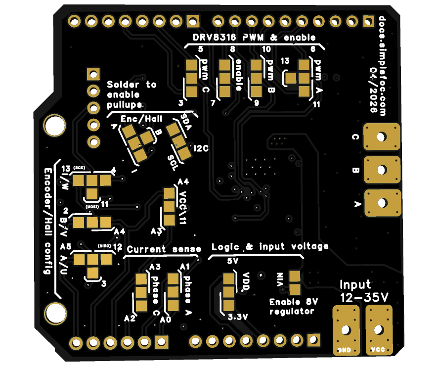
The solder pads let you:
- Configure the BLDC driver pinout (PWM A, B, C and enable) - Read more
- Configure the encoder/Hall sensor pinout - Read more
- Configure the current sensing pinout - Read more
- Enable the power supply voltage sensing and choose its pin - Read more new in v4
- Enable / disable the encoder/Hall sensor pull-up resistors - Read more
- Enable / disable the I2C pull-up resistors - Read more
- Enable / disable the on-board voltage regulator - Read more
- Set the logic voltage level VDD (3.3V or 5V) - Read more
Coming from v3?
The PWM, enable, encoder and current sense pads offer the same pin options as v3, so v3 pinouts and code carry over. The differences are:
- New power supply voltage sensing pad (
A3orA4)- No fault and reset pads: the DRV8316 fault output only drives the on-board LED
- The enable pin is required: it wakes the driver from sleep
- New current sense amplifiers, with a different gain in the code, see current sensing
Customizing the pinout
These are the configurable signals and their possible pins:
| Signal | Possible pins |
|---|---|
| PWM A | 6, 11, 13 |
| PWM B | 9, 10 |
| PWM C | 3, 5 |
| Enable | 7, 8 |
| Encoder A / Hall U | 3, 12, A5 |
| Encoder B / Hall V | 2, A4 |
| Encoder I / Hall W | 4, 11, 13 |
Solder exactly one pin for each signal you use. Not every combination works with every microcontroller:
- Arduino UNO has only two external interrupt pins,
2and3. When using an encoder or Hall sensors, use pin3for encoder A rather than for PWM C. - STM32 Nucleo (
STM32F4x) can’t generate PWM on pins11and9at the same time, so use pin13for PWM A instead of11. - SPI sensors use pins
11,12and13. If you use an SPI sensor (for example on the SPI connector), keep these pins free for SPI.
📢 If you’re not sure which pins to use, check our guide to choosing PWM pins!
The enable pin
On v4 the enable pin is connected to the nSLEEP input of the DRV8316 and pulled low on the board. The driver stays asleep, with all outputs off, until the microcontroller sets the enable pin high, so the enable pin must be soldered and given to the driver in the code:
BLDCDriver3PWM driver = BLDCDriver3PWM(6, 10, 5, 8); // PWM A, B, C, enable
The SimpleFOClibrary sets it high in driver.enable(), which is called by driver.init().
Configuring the current sensing pinout
The v4 has two INA240A2 current sense amplifiers (gain 50) with 5mΩ shunt resistors. Each amplifier output can be connected to one of two analog pins:
| Signal | Possible pins |
|---|---|
| Current sense 1 | A0, A1 |
| Current sense 2 | A2, A3 |
The measurement range depends on the logic voltage VDD: ±6.6A at 3.3V and ±10A at 5V.
When stacking two boards, make sure each board uses a different pair of pins.
📢 If you’re not sure which pins to use, check our guide to choosing ADC pins!
See writing the code for how to use the current sensing in your code.
Power supply voltage sensing
New in v4
The v4 has a voltage divider (47kΩ / 4.7kΩ) that measures the power supply voltage divided by 11. Solder its pad to connect it to one of these pins:
| Signal | Possible pins |
|---|---|
| Supply voltage / 11 | A3, A4 |
At the 35V maximum, the divider output is 3.2V, so it’s safe for 3.3V and 5V microcontrollers.
Both options share a pin with another function, so choose the one that’s free in your setup:
A3is also an option for current sense 2A4is also an option for encoder B, and it’s the I2CSDApin on Arduino UNO
When stacking two boards, enable the voltage sensing on only one board: both boards share the same power supply.
Encoder/Hall sensor pull-up resistors
The board has three 3.3kΩ pull-up resistors (to VDD) for encoder channels A, B and I (or Hall sensors U, V and W). Solder the pads to enable them.
Most encoders don’t need pull-ups, but a lot of low-cost open-collector encoders and Hall sensors do.
I2C pull-up resistors
The board has 4.7kΩ pull-up resistors (to VDD) for the I2C pins SDA and SCL, used by I2C sensors and the QWIIC/STEMMA connector. Solder the pads to enable them.
Arduino UNO usually works without them, but STM32 boards such as Nucleo-64 often need them for I2C magnetic sensors.
BEWARE: Stacking
If you are stacking two boards and need the I2C pull-ups, enable them on only one board.
On-board voltage regulator to power the MCU
The board has an 8V linear regulator (L78M08) from the power supply to the VIN pin of the Arduino headers. With its pad soldered, the shield powers the microcontroller board it is stacked on, so you don’t need a USB cable or a separate supply. Most boards with Arduino UNO headers accept up to 12V on VIN.
- The regulator needs about 10V or more at the power supply to output 8V.
- It can provide a few hundred mA at most, and gets hot with high supply voltages. It is meant to power the microcontroller board, not other loads.
BEWARE: Stacking
If you are stacking two boards, enable the regulator on only one board!
Logic voltage level VDD
VDD is the logic voltage of the board. It powers the current sense amplifiers, the pull-up resistors and the sensor connectors, so it has to match your microcontroller:
RULE OF THUMB: 3.3V or 5V
Arduino UNO (R3 and R4), Arduino MEGA - 5V
STM32 (Nucleo, Bluepill), ESP32 - 3.3V
Check your microcontroller’s datasheet before soldering this pad. A wrong VDD gives wrong current measurements and, with 5V on a 3.3V microcontroller, can damage its pins.
Suggested pinouts
Single board
When using one board, the main things to watch are to use pin 3 for encoder A (interrupts on Arduino UNO) and to keep 11, 12 and 13 free if you use an SPI sensor.
| Signal | PWM A | PWM B | PWM C | Enable | Enc. A | Enc. B | Enc. I | Current 1 | Current 2 | Voltage |
|---|---|---|---|---|---|---|---|---|---|---|
| Pin | 6 | 10 | 5 | 8 | 3 | 2 | 4 | A0 | A2 | A3 |
// driver: PWM A, B, C, enable
BLDCDriver3PWM driver = BLDCDriver3PWM(6, 10, 5, 8);
// encoder: A, B, CPR, I
Encoder sensor = Encoder(3, 2, 2048, 4);
For the current sensing and voltage sensing code, see writing the code.
Stacking with Arduino UNO
Arduino UNO has only 6 PWM pins, so two stacked boards need all of them. Use pin 3 for PWM C on one board, and don’t use pin 13 for PWM A.
| Signal | PWM A | PWM B | PWM C | Enable | Enc. A | Enc. B | Enc. I | Current 1 | Current 2 |
|---|---|---|---|---|---|---|---|---|---|
| Board #1 | 6 | 10 | 5 | 8 | 12 | 2 | 4 | A0 | A2 |
| Board #2 | 11 | 9 | 3 | 7 | A5 | A4 | 13 | A1 | A3 |
Stacking with STM32 Nucleo
Same as for Arduino UNO, but use pin 13 for PWM A on the second board instead of 11.
| Signal | PWM A | PWM B | PWM C | Enable | Enc. A | Enc. B | Enc. I | Current 1 | Current 2 |
|---|---|---|---|---|---|---|---|---|---|
| Board #1 | 6 | 10 | 5 | 8 | 12 | 2 | 4 | A0 | A2 |
| Board #2 | 13 | 9 | 3 | 7 | A5 | A4 | 11 | A1 | A3 |
When stacking two boards with encoders and current sensing on both, all the pins of the voltage sensing are already in use, so leave it disabled. With magnetic sensors instead of encoders, A4 is free (on boards where it isn’t the I2C pin) and can be used for the voltage sensing on one board.
// motor 1
BLDCDriver3PWM driver1 = BLDCDriver3PWM(6, 10, 5, 8);
Encoder sensor1 = Encoder(12, 2, 2048, 4);
// motor 2
BLDCDriver3PWM driver2 = BLDCDriver3PWM(13, 9, 3, 7);
Encoder sensor2 = Encoder(A5, A4, 2048, 11);