On this page
SimpleFOCNano

SimpleFOCNano is a small BLDC and stepper driver shield in the Arduino Nano form factor. You stack it with any Arduino Nano, from the original ATmega328 Nano to the Nano ESP32, connect a motor, a sensor and a power supply, and you have a complete motor controller. The board powers the Nano from the motor supply, and the SPI and I2C pins are routed to JST connectors, so sensors plug straight in.
The board was designed by runger and comes with its own driver class, SimpleFOCNanoDriver, in the SimpleFOCdrivers library, so you don’t have to set any pins.
Write the code GitHub project Order on Tindie
Features
- Driver: DRV8313, 3-PWM + 3-enable, 2.5A per phase
- Power supply: 8-30V
- Onboard buck converter: 8V to the Nano’s
VIN, through a diode, so USB can be connected at the same time - Power supply voltage sensing: VIN/10 on
A0 - Driver control: fault output, sleep and reset inputs connected to the Nano
- Logic level: 3.3V or 5V, set with a solder jumper
- Connectors: 6-pin JST SH for SPI sensors, 4-pin JST SH (STEMMA QT / QWIIC) for I2C sensors and modules
- LEDs: power and fault
- Compatible boards: all Arduino Nano boards: Nano, Nano Every, Nano 33 IoT, Nano 33 BLE, Nano RP2040 Connect, Nano ESP32, …
- Open source: designed in KiCad, all files on GitHub
The board has no current sensing, so it’s used with voltage torque control. It suits gimbal motors and other motors with a phase resistance above a few Ω, and it can also drive stepper motors.
Pinout
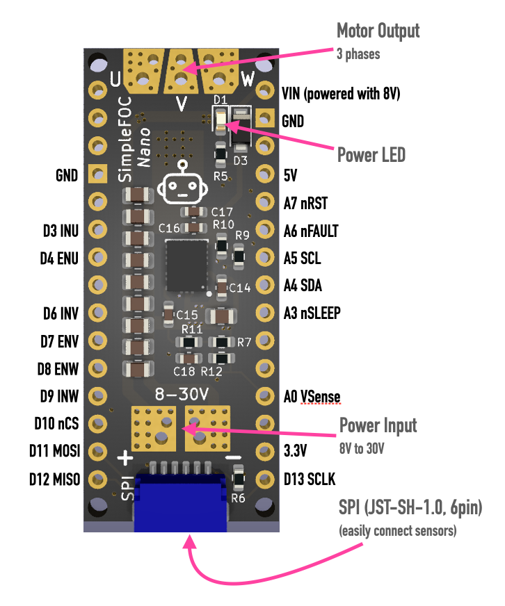
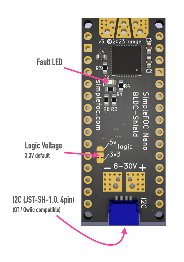
| Nano pin | Signal | Description |
|---|---|---|
D3 | IN U | Phase U PWM |
D6 | IN V | Phase V PWM |
D9 | IN W | Phase W PWM |
D4 | EN U | Phase U enable |
D7 | EN V | Phase V enable |
D8 | EN W | Phase W enable |
A0 | VBUS | Supply voltage sense: VIN/10 |
A3 | nSLEEP | Driver sleep, active low, 10kΩ pull-up |
A6 | nFAULT | Driver fault, active low, open drain |
A7 | nRESET | Driver reset, active low, 10kΩ pull-up |
VIN | 8V | From the onboard buck converter |
The serial pins RX / TX are free. The SPI and I2C pins are not used by the shield, they are routed to the JST connectors:
| Nano pin | Signal |
|---|---|
D10 | SPI CS (10kΩ pull-up) |
D11 | SPI MOSI |
D12 | SPI MISO |
D13 | SPI SCK |
A4 | I2C SDA |
A5 | I2C SCL |
The I2C pins have no pull-up resistors on the board. Most STEMMA QT / QWIIC modules have their own.
Setting up the hardware
Headers
The shield can sit on top of or below the Nano. If the boards came without headers, solder them so they match (male / female, orientation). For the motor and the power supply, solder 2.54mm headers, 3.5mm terminal blocks, or wires directly to the pads.
You can also wire the shield to any other microcontroller supported by SimpleFOC. In that case use BLDCDriver3PWM with your own pins instead of SimpleFOCNanoDriver.
Logic voltage: 3.3V or 5V
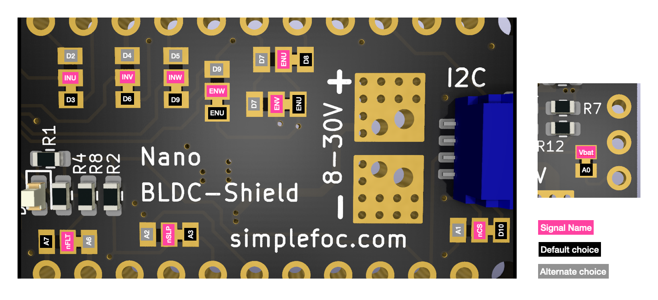
The solder jumper on the back sets the logic voltage. It’s 3.3V by default, which is right for all Nano boards except the original Nano and the Nano Every, which need 5V.
To change it, cut the trace between the centre pad and the 3.3V pad with a sharp knife, then bridge the centre pad and the 5V pad with solder. Check with a multimeter that the old connection is open and the new one is closed.
Power supply
The supply range is 8-30V; the driver starts working at around 7V. The buck converter makes 8V for the Nano’s VIN. Below 8V it passes the input voltage through, and about 5V is enough for all Nano boards. With batteries, use 3S to 6S: 2S may be too little for the driver once it’s partly discharged.
When you power the shield, the power LEDs on both the shield and the Nano should light up.
Sensor
The easiest option is an SPI magnetic sensor, such as the AS5048A or AS5047, on the 6-pin JST connector, with chip select on D10. I2C sensors such as the AS5600 plug into the STEMMA QT connector. Depending on the Nano, the free pins can also be used for an encoder.
On the 5V boards (Nano, Nano Every), use a sensor that works at 5V.
Writing the code
Install the SimpleFOClibrary and the SimpleFOCdrivers library. The SimpleFOCNanoDriver class is a BLDCDriver3PWM with the shield’s pins already set.
Step 1. Test the motor in open loop
#include <SimpleFOC.h>
#include <SimpleFOCDrivers.h>
#include <drivers/simplefocnano/SimpleFOCNanoDriver.h>

BLDCMotor motor = BLDCMotor(7); // set your motor's pole pair number
SimpleFOCNanoDriver driver = SimpleFOCNanoDriver();

// commander interface
Commander command = Commander(Serial);
void onTarget(char* cmd){ command.scalar(&motor.target, cmd); }

void setup() {
  Serial.begin(115200);
  SimpleFOCDebug::enable(&Serial);

  // measure the supply voltage: logic voltage (5V for the classic Nano), ADC resolution
  driver.voltage_power_supply = driver.getBusVoltage(5.0f, 1024);
  driver.init();
  motor.linkDriver(&driver);

  motor.voltage_limit = 1;   // [V] keep the motor cool
  motor.controller = MotionControlType::velocity_openloop;
  motor.init();

  motor.target = 2; // [rad/s]
  command.add('T', onTarget, "target velocity");
  Serial.println("Motor ready! Set the target with T, e.g. T5");
}

void loop() {
  motor.move();
  command.run();
}
getBusVoltage(vdd, resolution) reads the supply voltage on A0. Give it the logic voltage and the ADC resolution of your Nano:
| Board | Call |
|---|---|
| Nano, Nano Every (5V, 10-bit) | driver.getBusVoltage(5.0f, 1024) |
3.3V boards, default 10-bit analogRead() | driver.getBusVoltage(3.3f, 1024) |
3.3V boards with analogReadResolution(12) | driver.getBusVoltage(3.3f, 4096) |
It averages 500 readings, so it’s slow: call it in setup(), not while the motor is running.
Step 2. Close the loop
With an SPI sensor on the JST connector, the full code is:
#include <SimpleFOC.h>
#include <SimpleFOCDrivers.h>
#include <drivers/simplefocnano/SimpleFOCNanoDriver.h>

BLDCMotor motor = BLDCMotor(7); // set your motor's pole pair number
SimpleFOCNanoDriver driver = SimpleFOCNanoDriver();

// SPI magnetic sensor on the JST connector, chip select D10
MagneticSensorSPI sensor = MagneticSensorSPI(AS5048_SPI, PIN_nCS);

// commander interface
Commander command = Commander(Serial);
void onTarget(char* cmd){ command.scalar(&motor.target, cmd); }

void setup() {
  Serial.begin(115200);
  SimpleFOCDebug::enable(&Serial);

  sensor.init();
  motor.linkSensor(&sensor);

  // logic voltage (5V for the classic Nano, 3.3V for the others), ADC resolution
  driver.voltage_power_supply = driver.getBusVoltage(5.0f, 1024);
  driver.init();
  motor.linkDriver(&driver);

  motor.torque_controller = TorqueControlType::voltage;
  motor.controller = MotionControlType::velocity;
  motor.voltage_limit = 3;        // [V]
  motor.voltage_sensor_align = 2; // [V]
  motor.velocity_limit = 20;      // [rad/s]
  motor.PID_velocity.P = 0.2f;
  motor.PID_velocity.I = 5;
  motor.LPF_velocity.Tf = 0.01f;

  motor.init();
  motor.initFOC();

  motor.target = 2; // [rad/s]
  command.add('T', onTarget, "target velocity");
  Serial.println("Motor ready! Set the target with T, e.g. T5");
}

void loop() {
  motor.loopFOC();
  motor.move();
  command.run();
}
Original Nano (ATmega328P)
This code uses about 98% of the original Nano’s flash, so there’s little room for more. To use the full Commander interface and monitoring, choose a bigger Nano, such as the Nano ESP32, the Nano RP2040 Connect or the Nano 33 IoT.
Using a stepper motor
The shield can also drive a 2-phase stepper motor with the HybridStepperMotor class. Connect the motor in the order A+, A-/B-, B+: one wire of each coil to the outer outputs, and the other wire of both coils together to the middle output:
| Motor output | Stepper wires |
|---|---|
U | A+ |
V | A- and B- together (common) |
W | B+ |
To find which wires belong to the same coil, measure with a multimeter: the two wires of a coil have a few Ω between them, wires of different coils are not connected. Steppers have a low phase resistance, so limit the voltage in the code to stay below the motor’s rated current: voltage_limit = rated current × phase resistance.
As V is the common, use BLDCDriver3PWM with the pins in the order U, W, V, instead of SimpleFOCNanoDriver. The pin constants from the driver header still work, and the sleep and reset pins have pull-ups, so the driver runs without the helper class:
#include <SimpleFOC.h>
#include <SimpleFOCDrivers.h>
#include <drivers/simplefocnano/SimpleFOCNanoDriver.h>

// stepper motor: 50 pole pairs for a 200 step/rev stepper
HybridStepperMotor motor = HybridStepperMotor(50);
// PWM and enable pins in the order A+ (U), B+ (W), common (V)
BLDCDriver3PWM driver = BLDCDriver3PWM(PIN_INU, PIN_INW, PIN_INV, PIN_ENU, PIN_ENW, PIN_ENV);

// SPI magnetic sensor on the JST connector, chip select D10
MagneticSensorSPI sensor = MagneticSensorSPI(AS5048_SPI, PIN_nCS);

// commander interface
Commander command = Commander(Serial);
void onTarget(char* cmd){ command.scalar(&motor.target, cmd); }

void setup() {
  Serial.begin(115200);
  SimpleFOCDebug::enable(&Serial);

  sensor.init();
  motor.linkSensor(&sensor);

  driver.voltage_power_supply = 12; // your power supply voltage
  driver.init();
  motor.linkDriver(&driver);

  motor.torque_controller = TorqueControlType::voltage;
  motor.controller = MotionControlType::velocity;
  motor.voltage_limit = 2;        // [V] keep the current below your motor's rating
  motor.voltage_sensor_align = 2; // [V]
  motor.velocity_limit = 20;      // [rad/s]

  motor.init();
  motor.initFOC();

  motor.target = 2; // [rad/s]
  command.add('T', onTarget, "target velocity");
  Serial.println("Motor ready! Set the target with T, e.g. T5");
}

void loop() {
  motor.loopFOC();
  motor.move();
  command.run();
}
Fault, sleep and reset
SimpleFOCNanoDriver also handles the DRV8313 fault, sleep and reset pins:
// check for a fault and clear it
if (driver.isFault()) {
  motor.disable();
  driver.clearFault();
}

// put the driver to sleep to save power, and wake it up
driver.sleep();
if (driver.isSleeping()) driver.wake();
Fault pin on the original Nano
On the ATmega328P,
A6andA7are analog-only pins, soisFault()(a digital read ofA6) doesn’t work there, and the reset pinA7can’t be driven (its pull-up keeps the driver running). Read the fault withanalogRead(A6) < 200instead. The other Nano boards support digital reads on these pins.
Board-specific notes
The shield was tested in closed loop with an SPI sensor on these boards. See the compatibility notes for the details and example platformio.ini files.
| Board | Status | Notes |
|---|---|---|
| Nano (ATmega328P) | ✔️ | ~1kHz loop, 5V logic, little flash left |
| Nano ESP32 | ✔️ | ~8kHz loop. With MCPWM, older library versions needed the GPIO numbers for the PWM pins |
| Nano RP2040 Connect | ✔️ | ~3kHz loop. Use the GPIO numbers for the PWM pins, and 17 / 21 for A3 / A7 |
| Nano 33 IoT | ✔️ | Phase U PWM isn’t aligned with the other phases, but the motor runs fine |
| Nano 33 BLE | ✔️ | Works in the Arduino IDE; not in PlatformIO at the time of testing |
| Nano Every | ⚠️ | No PWM driver for this MCU in the library yet |
How to get one
- Order the assembled board on Tindie.
- Make it yourself: the KiCad project, BOM and placement files are in the GitHub repository.