On this page
Getting started with SimpleFOC QtFOC
QtFOC has a fixed pinout, so there’s nothing to configure: plug in your XIAO or QT Py, connect the motor, the sensor and the power supply, and upload the code.
1. Pinout
The board uses the standard XIAO / QT Py pinout:
| XIAO / QT Py pin | Signal | Description |
|---|---|---|
A0 / D0 | SOA | Phase A current sense |
A1 / D1 | SOB | Phase B current sense |
A2 / D2 | VSENS | Supply voltage sense: VIN/11 |
D3 | IN1 | Phase A PWM (terminal M1) |
D4 | IN2 | Phase B PWM (terminal M2) |
D5 | IN3 | Phase C PWM (terminal M3) |
D6 / TX | TX | UART TX (header) |
D7 / RX | CS / RX | SPI sensor chip select, UART RX (header) |
D8 | SCK | SPI clock |
D9 | MISO | SPI MISO |
D10 | MOSI | SPI MOSI |
5V | 5V | From the DRV8316 buck converter, through a diode |
3V3 | 3.3V | From the MCU board’s regulator, powers the sensor |
The driver has no enable pin: it is always on when the board is powered.
D7 is shared between the SPI chip select and RX of the UART header, so you can use only one of them at a time.
2. Connect the hardware
Power supply
Connect an 8-35V supply to the screw terminal VCC / GND. The board makes 5V from it and powers the XIAO / QT Py, so you can unplug the USB cable once the board is programmed.
USB and the power supply can be connected at the same time. The 5V buck gives up to 200mA, so when you use the WiFi or BLE radio of an ESP32 board, also power the MCU board from USB.
BLDC motor
Connect the three motor phases to M1, M2 and M3, in any order.
BEWARE: Power limits
The DRV8316 gives up to 8A peak; the continuous current depends on cooling, and the board is small. With low-resistance motors (R < 1Ω), always limit the current or voltage in the code. For more about choosing a motor, see the BLDC motor docs.
Stepper motor
The board can also drive a 2-phase stepper motor, using the HybridStepperMotor class. Connect the motor in the order A+, A-/B-, B+: one wire of each coil to the outer terminals, and the other wire of both coils together to the middle terminal:
| Motor terminal | Stepper wires |
|---|---|
M1 | A+ |
M2 | A- and B- together (common) |
M3 | B+ |
- It doesn’t matter which wire of a coil is
+or-, as long as both coils share the common terminal. - To find which wires belong to the same coil, measure with a multimeter: the two wires of a coil have a few Ω between them, wires of different coils are not connected.
- Steppers have a low phase resistance, typically 1-3Ω, so always limit the current or voltage in the code to the rated current of the motor.
SPI sensor
The 6-pin JST SH (1mm pitch) connector is made for SPI magnetic sensors, such as the AS5047, AS5048A, MT6701 or MT6835:
| Pin | 1 | 2 | 3 | 4 | 5 | 6 |
|---|---|---|---|---|---|---|
| Signal | GND | 3.3V | D10 (MOSI) | D9 (MISO) | D8 (SCK) | D7 (CS) |
Other sensors
- Encoder or Hall sensors: there are only two free pins,
D6andD7, on the UART header. That’s enough for an encoder A/B (without index), but not together with an SPI sensor. Check that your MCU supports interrupts on these pins, and use 3.3V encoders. - PWM sensors (e.g. AS5600, MT6701 in PWM mode): one pin,
D6orD7. - I2C sensors: see below.
I2C sensors on the STEMMA QT connector
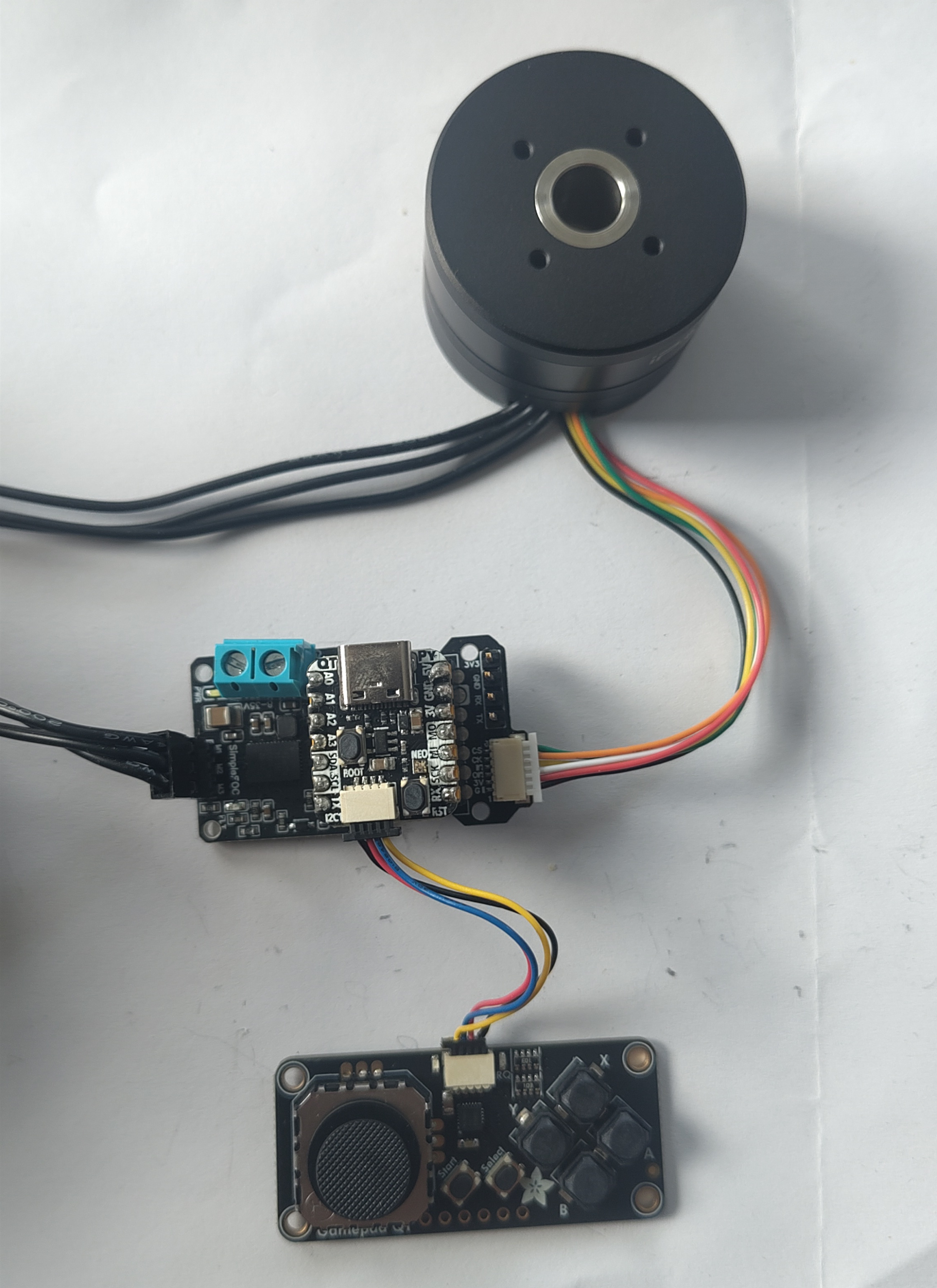
The I2C pins of the header (D4 / D5) drive the motor, so I2C sensors can’t use them. Most Adafruit QT Py boards (RP2040, ESP32-S2, ESP32-S3, …) have a STEMMA QT connector on a separate I2C bus (Wire1), which you can use for an I2C sensor or other I2C devices, for example an I2C gamepad. Check the pinout of your QT Py, some boards share the STEMMA QT pins with D4 / D5.
MagneticSensorI2C sensor = MagneticSensorI2C(AS5600_I2C);

// in setup()
Wire1.begin();
sensor.init(&Wire1);
3. Write the code
The examples below use an SPI sensor on the JST connector. They were compiled for the XIAO ESP32-S3, and use the Dx / Ax pin names, which all XIAO and QT Py Arduino cores define.
Step 1. Test the motor in open loop
Start without a sensor, to check that the driver and the motor work:
#include <SimpleFOC.h>

// BLDC motor & driver instance
BLDCMotor motor = BLDCMotor(7); // set your motor's pole pair number
BLDCDriver3PWM driver = BLDCDriver3PWM(D3, D4, D5);

// commander interface
Commander command = Commander(Serial);
void onTarget(char* cmd){ command.scalar(&motor.target, cmd); }

void setup() {
  Serial.begin(115200);
  SimpleFOCDebug::enable(&Serial);

  driver.voltage_power_supply = 12; // your power supply voltage
  driver.init();
  motor.linkDriver(&driver);

  // limit the voltage to keep the motor and the driver cool
  motor.voltage_limit = 1;   // [V]
  motor.controller = MotionControlType::velocity_openloop;
  motor.init();

  motor.target = 2; // [rad/s]
  command.add('T', onTarget, "target velocity");
  Serial.println("Motor ready! Set the target with T, e.g. T5");
}

void loop() {
  motor.move();
  command.run();
}
The motor should turn slowly and smoothly. If it vibrates or doesn’t move, check the pole pairs number and the connections, and raise voltage_limit a bit. See the open-loop examples for more.
Step 2. Test the sensor
#include <SimpleFOC.h>

// SPI magnetic sensor on the JST connector, chip select D7
MagneticSensorSPI sensor = MagneticSensorSPI(AS5047_SPI, D7);

void setup() {
  Serial.begin(115200);
  sensor.init();
  Serial.println("Sensor ready");
}

void loop() {
  sensor.update();
  Serial.print(sensor.getAngle());
  Serial.print("\t");
  Serial.println(sensor.getVelocity());
  delay(10);
}
Turn the motor by hand: the angle should change by 6.28 radians per turn. For other sensors, see the position sensor docs.
Step 3. Current sensing
The DRV8316 measures the currents of phases A and B on the low side, with a gain of 150mV/A. Use them with LowsideCurrentSense:
// DRV8316 low-side current sensing: 150mV/A, phases A and B
LowsideCurrentSense current_sense = LowsideCurrentSense(150.0f, A0, A1);
// in setup(), after driver.init()
current_sense.linkDriver(&driver);
current_sense.init();
motor.linkCurrentSense(¤t_sense);
motor.torque_controller = TorqueControlType::foc_current;
The current sensing has to be supported by your MCU, see the compatible boards. If it isn’t (e.g. RP2040, ESP32-C3), leave the current sensing out and use voltage torque control, with motor.voltage_limit to limit the current. See torque control for the differences.
Step 4. Power supply voltage sensing
The board measures the supply voltage divided by 11 on A2. Read it in setup(), before the current sensing starts, to set the driver’s supply voltage:
// supply voltage sensing: VIN/11 on A2
float readSupplyVoltage() {
  return analogRead(A2) * 3.3f / 4095.0f * 11.0f;
}

// in setup(), before driver.init()
analogReadResolution(12);
driver.voltage_power_supply = readSupplyVoltage();
To read it in loop() while the motor runs, don’t use analogRead(), as it can interfere with the low-side current sensing. See regular ADC reads during FOC.
Full code
The full code with the SPI sensor, current sensing, voltage sensing and the Commander interface. It works directly with the SimpleFOC web controller:
#include <SimpleFOC.h>
// BLDC motor & driver instance
BLDCMotor motor = BLDCMotor(7); // set your motor's pole pair number
BLDCDriver3PWM driver = BLDCDriver3PWM(D3, D4, D5);
// SPI magnetic sensor on the JST connector, chip select D7
MagneticSensorSPI sensor = MagneticSensorSPI(AS5047_SPI, D7);
// DRV8316 low-side current sensing: 150mV/A, phases A and B
LowsideCurrentSense current_sense = LowsideCurrentSense(150.0f, A0, A1);
// commander interface
Commander command = Commander(Serial);
void doMotor(char* cmd){ command.motor(&motor, cmd); }
// supply voltage sensing: VIN/11 on A2
float readSupplyVoltage() {
return analogRead(A2) * 3.3f / 4095.0f * 11.0f;
}
void setup() {
Serial.begin(115200);
SimpleFOCDebug::enable(&Serial);
// initialise the sensor
sensor.init();
motor.linkSensor(&sensor);
// driver: measure the supply voltage before starting the current sensing
analogReadResolution(12);
driver.voltage_power_supply = readSupplyVoltage();
driver.init();
motor.linkDriver(&driver);
// current sensing
current_sense.linkDriver(&driver);
current_sense.init();
motor.linkCurrentSense(¤t_sense);
// control loop configuration
motor.torque_controller = TorqueControlType::foc_current;
motor.controller = MotionControlType::velocity;
motor.current_limit = 2; // [A]
motor.voltage_sensor_align = 1; // [V]
motor.velocity_limit = 20; // [rad/s]
// monitoring, for the web controller
motor.useMonitoring(Serial);
motor.monitor_start_char = 'M';
motor.monitor_end_char = 'M';
motor.monitor_downsample = 0; // enable from the web controller
motor.init();
motor.initFOC();
motor.target = 2; // [rad/s]
command.add('M', doMotor, "motor");
Serial.println("Motor ready!");
}
void loop() {
motor.loopFOC();
motor.move();
motor.monitor();
command.run();
}
Using a stepper motor
With the stepper connected as A+ on M1, the common on M2 and B+ on M3, use HybridStepperMotor and give the PWM pins in the order A+, B+, common: D3, D5, D4. The current sensing is the same as for a BLDC motor; the library finds which phase is measured during the alignment.
#include <SimpleFOC.h>
// stepper motor & driver instance
HybridStepperMotor motor = HybridStepperMotor(50); // 50 pole pairs for a 200 step/rev stepper
// PWM pins in the order A+, B+, common: M1 = D3, M3 = D5, M2 = D4
BLDCDriver3PWM driver = BLDCDriver3PWM(D3, D5, D4);
// SPI magnetic sensor on the JST connector, chip select D7
MagneticSensorSPI sensor = MagneticSensorSPI(AS5047_SPI, D7);
// DRV8316 low-side current sensing: 150mV/A, phases A and B
LowsideCurrentSense current_sense = LowsideCurrentSense(150.0f, A0, A1);
// commander interface
Commander command = Commander(Serial);
void doMotor(char* cmd){ command.motor(&motor, cmd); }
void setup() {
Serial.begin(115200);
SimpleFOCDebug::enable(&Serial);
sensor.init();
motor.linkSensor(&sensor);
driver.voltage_power_supply = 12; // your power supply voltage
driver.init();
motor.linkDriver(&driver);
current_sense.linkDriver(&driver);
current_sense.init();
motor.linkCurrentSense(¤t_sense);
motor.torque_controller = TorqueControlType::foc_current;
motor.controller = MotionControlType::velocity;
motor.current_limit = 1; // [A] your motor's rated current
motor.voltage_sensor_align = 2; // [V]
motor.velocity_limit = 20; // [rad/s]
motor.useMonitoring(Serial);
motor.monitor_start_char = 'M';
motor.monitor_end_char = 'M';
motor.monitor_downsample = 0;
motor.init();
motor.initFOC();
motor.target = 2; // [rad/s]
command.add('M', doMotor, "motor");
Serial.println("Motor ready!");
}
void loop() {
motor.loopFOC();
motor.move();
motor.monitor();
command.run();
}
See the stepper motor docs for more about HybridStepperMotor.